
Installation Guide and Manual


50
Electrical Supply Requirements
General Wiring Requirements
WARNING
THIS DEVICE CONTAINS ELECTRICAL PARTS
WHICH CAN CAUSE SHOCK OR INJURY.
All electrical connections, conduit and fittings on the protected
enclosure must be suitable for the hazardous location in which
they are installed. In addition, all conduit and wire must be
installed in accordance with NEC as required and all relevant plant
and local codes. Note: Do not use seals on conduit used as a
protected "wireway" to supply protective gas to adjacent
protected enclosures. The same conduit can be utilized for both
electrical and pneumatic service to an adjacent protected
enclosure(s), provided the conduit is oversized to allow a
minimum free clearance equal to or larger than the pipe size
required between multiple enclosures.
Enclosure Power Requirements
The protected enclosure(s) electrical power source must originate
from a circuit breaker or fused disconnect suitable for the
hazardous location in which it is installed. The switch must be
located within fifty (50) (15.2 m) feet of the protected enclosure(s)
and the protection system and be properly marked.
Alarm Signal Requirements
The WPSA style pressure switch requires a 120 VAC power supply
in addition to the alarm signal. The WPS and WPSA Style system
alarm signal may originate from the protected enclosure if the
alarm signal is disconnected by the protected enclosure's circuit
breaker or fused disconnect as stated in Enclosure Power
Requirements above.
The protected enclosure(s) alarm signal power may also originate
from outside of the protected enclosure. In this application, the
protected enclosure may be used as a "wireway" to pass alarm
signal wiring from the power source to the alarm device, if the
wiring is isolated and properly labeled. In addition, appropriate
conduit seals must be provided outside of the protected enclosure
separately.
Important Note
NFPA 496 requires the use of an alarm or an indicator to detect
the loss of safe enclosure pressure. In addition, the NFPA 496
requires that if an indicator alone is utilized, a protective gas
supply alarm must also be installed between the last valve in
the protective gas supply and the protected enclosure.
Therefore, the protective gas supply to all LPS Style systems
must be equipped with the above mentioned protective gas
supply alarm. Exception: Systems utilizing an EPSK or GPSK
enclosure pressure loss alarm switch accessory will satisfy the
above mentioned NFPA requirement.
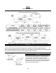
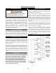
Typical Enclosure Wiring Methods
In a general sense, protected enclosures should be wired similar
to explosion proof enclosures, in accordance with Article 500 of
the National Electric Code - NFPA 70.
Single conductor wiring should be placed in rigid metal conduit,
seal-flex conduit or other mediums approved for use in the
hazardous location surrounding the protected enclosure.
Additionally, NFPA 496 requires the use of approved seals on all
pressurized enclosure conduit wiring entries, in accordance with
NFPA 70. Furthermore, the use of an approved seal is simply the
most practical way to prevent excessive leakage through conduit
connections.
However, while explosion proof enclosures require conduit seals
on all cable entries, in accordance with NFPA 70, other methods of
sealed cable entries that are suitable for hazardous locations can
be used, such as compression glands.
In conclusion, there are two primary goals. First, the installer
should ensure that all associated wiring and cable is protected by
pressurization or other means, such as explosion proof conduit or
intrinsic safety barriers. Secondly, the installer should ensure that
all associated conduit and wireways are sealed to conserve
protective gas, unless they are used to supply protective gas to
other enclosures or devices.
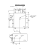
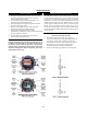
Typical Enclosure Wiring Connections