
Installation Guide and Manual


19
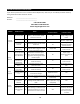
Flow rate is too
high
A14
Check LOAD PCT for 100% load
Reduce flow rate, heater is
operating outside of
capability
A15
Element failure
A15
Power off, Using a multimeter check
continuity at between red and black
wires at each element chamber
A16
No continuity- replace
heater element. Check
water quality
Heating Elements
not modulating
A16
Verify SSR/Triac functionality by
checking current draw off each
SSR/Triac by means of an amp
clamp. Also verify signal wires are
connected from PCB P2, P3, and P4.
No current draw-
replace SSR/ Triac
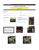
Display
FAULT
Ambient light is
causing the optical
(overheat) sensors
to trip.
A17
Unit is to be operated with the
cover on or (if NEMA equipped)
door closed when power is applied
to the unit.
A18
Close door, or reinstall
cover
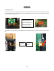
Air is present in the
heating chamber
A18
Verify air is not present in the
system by checking for a red led
light on the heating chamber. Look
between the black manifolds into
the clear tube sections for air
bubbles.
Remove air by installing an
air scrubber prior to heater,
or flushing system
thoroughly before use.
Check all wire connections
Replace light sensor
board
Loose /cut wire to
optical sensors
A19
Verify 5VDC is present on the last
optical sensor in the chain by using a
multimeter set for dc voltage at the
connector P12 with one meter lead
on the red wire and the other on the
black wire.
Check A17 and A18 again
Call Eemax for support
Display
FAULT F3
Multiple dry fire
conditions
detected (FAULT
F2) more than 3
times
A20
Recheck actions A17-A19. Shut
down power and restart.
Replace main PCB and
light sensor boards
Display
FAULT F4
Inlet thermistor out
of range
A21
Verify inlet thermistor is properly
seated in thermal well
Verify inlet temperature is
not below freezing, above
set point temperature, or
heater is piped backwards
Replace thermistor
inlet or outlet or both
No heat
Turn-on flow rate
not satisfied
A22
Toggle through display to verify
FLOWRATE and TURN-ON
Increase water flow rate
above TURN-ON setting
Check wiring to
flowmeter.
Display states
FLOW ???
A23
Power off unit, and verify no faults
are found. Verify flow meter harness
is seated in terminal P12 on the
main PCB and at flow meter PCB
Call Eemax for support,
firmware reload may be
required
If faults found
reference above
Note: Error code history is not self-clearing. Unit keeps track of past errors. Error codes do not necessarily mean
there is a current error.