
Installation Guide and Manual


18
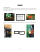
TROUBLESHOOTING PROCEDURES
If you need any assistance from our Technical Service Department, make sure you can identify this water heater by
having the model number and serial number.
Model No. ______________________________
Serial No. ______________________________
Call 203-267-7890
TOLL FREE: 1-800-543-6163
Eemax.Support@eemax.com
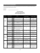
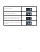
PROBLEM
POSSIBLE CAUSES
Action
IF TRUE
Proceed to Action
IF FALSE
Proceed to Action
Unit does
not power
on
Main Power issue
A1
Check main power supply voltage is
within +/- 5% of nominal. Check
breaker and wire size.
A2
Provide the correct
supply voltage to the
heater
Blown Fuse
A2
Check all fuses for continuity
A3
Check voltages and
elements, replace fuse
Transformer
overload
A3
Check circuit breaker on 24V control
transformer
A4
Check voltages and for
failed PCB, Contactors-
reset transformer
Printed circuit
board (PCB)
A4
Verify main PCB is plugged in at P16
Replace PCB
Check connection, and
reset connector
Display
ERROR E1
Water temperature
entering heater is
above SETPOINT
A5
Verify supply water supply
temperature is below set point.
Note - Heater will automatically
engage when incoming water drops
below set point.
A6
Adjust supply
temperature below set
point
Loose PCB
connection or
pinched wire
A6
Check PCB connection at P7 and
check wire routing
A7
Check connection, and
reset connector
Inlet thermistor
failure
A7
Check thermistor for proper
placement in well
Replace thermistor
Re-seat thermistor in
well
Display
FAULT F0
Outlet thermistor
out of range
A8
Check PCB connection at P7 and
check wire routing
A9
Check connection, and
reset connector
Outlet thermistor is
damaged or wire is
cut
A9
Check thermistor, wire, or
connector for damage
Replace thermistor
A10
Heater is frozen
A10
Verify supply and feed lines are not
frozen
Un-freeze heater and check
functionality
Display
FAULT F1
No change in water
temperature
detected
A11
Verify change in temperature by
checking ACTUAL TEMP vs INLET
TEMP
Lower flow rate to allow
heater to operate in range
of capability
A12
Thermistor failure
A12
Follow actions A5-A7
A13
Thermal trip at
ECO/ Damaged
wire
A13
Power off, Using a multimeter check
continuity at PCB P17 pins 1 and 3.
Check all wires for loose connection
A14
No continuity verifies a
thermal trip. Shut down
power and allow to
cool. Verify connector
is seated