
Installation Guide and Manual


15
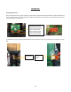
CONTROL FEATURES
CAUTION
BEFORE USING THIS CONTROL, make sure all prior installation steps have been
properly completed, electrical power is on and water is present in the heater.
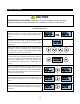
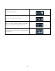
Push Button Flow Chart
1) The SETPOINT TEMP or ACTUAL TEMP screen can be
selected for display as the home screen. Either of these
screens will remain on the display when the backlight timer
expires.
OR
2) There is a 5-minute time delay built into the control.
Regardless of which screen is being displayed, after 5
minutes of inactivity, the display will revert to the SETPOINT
TEMP screen.
3) The 4 push buttons are used to control the operation of
the heater. The LEFT and RIGHT buttons shift the display
from one screen to another. The DOWN and UP buttons may
change the values within selected screens.
4) As an example, when the screen displays SETPOINT TEMP,
the desired hot water temperature will increase 1 degree for
each press of the UP button and decrease 1 degree for each
press of the DOWN button. Note that minimum and
maximum set point temperatures are established at the
factory.
5) The LEFT and RIGHT buttons shift the display from one
screen to another. From the INLET TEMP screen, one press
of the RIGHT button will shift the display to the SETPOINT
TEMP screen. INLET TEMP shows the actual temperature of
the water entering the heater.
6) From the SETPOINT TEMP screen, one press of the RIGHT
button will shift the display to the ACTUAL TEMP screen. This
shows the actual temperature of the water leaving the
heater.
7) Form the ACTUAL TEMP screen, one press of the RIGHT
button will shift the display to the LOAD PCT screen. This
shows the electrical power consumption as a percentage of
full power.
ACTUAL
TEMP 75F
SETPOINT
TEMP120F
SETPOINT
TEMP120F
SETPOINT
TEMP120F
SETPOINT
TEMP120F
INLET
TEMP 75F
ACTUAL
TEMP 75F
SETPOINT
TEMP120F
LOAD PCT
0% PWR
ACTUAL
TEMP 75F