
Cut Sheet

Data Sheet S85001-0611 Issue 1
Not to be used for installation purposes. Page 6 of 6
U.S.
T 800-336-4206
F 800-454-2363
Canada
T 519 376 2430
F 519 376 7258
Asia
T 852 2907 8108
F 852 2142 5063
Australia
T 61 3 9259 4700
F 61 3 9259 4799
Europe
T 32 2 725 11 20
F 32 2 721 86 13
Latin America
T 305 593 4301
F 305 593 4300
www.edwardssignaling.com
© 2008 General Electric Company
All Rights Reserved
GE
Security
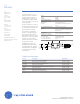
Ordering Information
Model Description Ship Weight
E-IDC1A Analog Class A Single Input Module 0.50 lbs. (0.23 kg.)
E-IDC1B Analog Single Input Mini Module 0.34 lbs. (0.15 kg.)
E-2WIRE* Analog Class A-B Two-Wire Module 0.50 lbs. (0.23 kg.)
E-IDC2B Analog Dual Input Module 0.50 lbs. (0.23 kg.)
E-2IDCWS Analog Dual Input Waterflow-Supervisory Module 0.50 lbs. (0.23 kg.)
E-NAC Analog NAC Module 0.50 lbs. (0.23 kg.)
E-RLY Analog Contact Relay Module 0.50 lbs. (0.23 kg.)
E-ISO Analog SLC Fault Isolator Module 0.50 lbs. (0.23 kg.)
*Available Q1, 2009
Communication line voltage Maximum 20 V peak-to-peak
Current
Standby
Activated
350 μA
500 μA
Ground fault impedance 10 k ohm
Operating environment
Temperature
Humidity
32 to 120°F (0 to 49°C)
0 to 93% RH, noncondensing at 90°F
(32°C)
Storage temperature range –4 to 140°F (–20 to 60°C)
Wire size 12, 14, 16, or 18 AWG wire (2.5, 1.5, 1.0,
or 0.75 sq. mm) (Sizes 16 and 18 AWG
are preferred)
Device address
(two addresses required)
01 to 64 (64 point control panel)
01 to 127 (127 point control panel)
Initiating device circuit (IDC)
EOL resistor value
Max. circuit resistance
Max. circuit capacitance
47 kΩ, (P/N: EOL-47)
50 Ω (25 Ω per wire)
0.1 μF
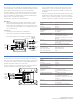
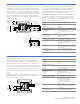
Single Input Mini Module
E-IDC1B
The E-IDC1B connects a nor-
mally open, alarm, supervisory,
or monitor type dry contact
initiating device circuit (IDC) to
the Edwards Signaling control
panel. This module is for Class B
circuit operation.
The device address is set using
the two rotary switches located
on the front of the module. One
device address is required.
The module is configured to
operate as an alarm latching
device type from the factory.
When the NO contact of an initi-
ating device is closed, an alarm
signal is sent to the control
panel and the alarm condition is
latched at the module.
Additional device types are
available through front panel
programming or the configura-
tion utility. Refer to applicable
control panel technical refer-
ence manual.
Red (+)
IDC (+)
Orange
IDC
Yellow
0
1
2
3
4
5
6
12
11
10
9
8
7
0
9
1
2
3
4
5
6
7
8
47
EOLR
k Ohm
Typical NO
initiating device
From
previous
device
SLC in
SLC out
Wire nut
SLC in (+)
SLC out (+)
To next
device
Style B (Class B)
Black
( )
( )
( )
( )
Insert screwdriver here
LEDs on reverse side