
Cut Sheet
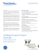

Data Sheet S85001-0611 Issue 1
Not to be used for installation purposes. Page 5 of 6
NAC Module
E-NAC
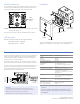
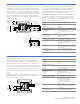
The E-NAC connects a supervised output circuit to a signal riser. The
output wiring is monitored for open and short circuits. A short cir-
cuit causes the module to inhibit the activation of the audible/visual
signal circuit so the riser is not connected to the wiring fault. Upon
command from the control panel, the module connects the output
circuit to the riser input. The output circuit energizes a riser to oper-
ate polarized audible and visual signals. The module can be used
for connection of a Class A or Class B (with EOL) output notification
appliance circuit (NAC).
The E-NAC is configured to operate as a Genesis Audible/Visual/
Silence device type from the factory. It can also be configured
for other device types through front panel programming or the
configuration utility. Refer to the applicable control panel technical
reference manual for a list of available device types.
Genesis Audible/Visual/Silence: Used with Genesis and Enhanced
Integrity horns and strobes. Signals maintain synchronization per
UL 1971. For Genesis devices, this configuration allows connected
horns to be silenced while strobes on the same two-wire circuit
continue to flash until the panel is reset.
From
listed
power
supply
[4]
24 VDC (+)
24 VDC
Circuit wired
same as
diagram above
Style Z (Class A)
Style Z (Class A)
Style Y (Class B)
Style Y (Class B)
Typical bell circuit
Typical horn or
strobe circuit
TB2 TB1
+ +
- -
+ +
- -
+ +
-
-
RETURN
NAC PWR. IN
NAC
SLC
(+)
(+)
From
previous
device
To next
device
SLC out (+)
SLC out
SLC in
SLC in (+)
( )
( )
( )
( )
( )
( )
( )
47 k Ohm ELOR
used for
Class B only
47 k Ohm ELOR
used for
Class B only
Communication line voltage Maximum 20 V peak-to-peak
Current
Standby
Activated
350 μA
200 μA
Ground fault impedance 10 k ohm
Operating environment
Temperature
Humidity
32 to 120°F (0 to 49°C)
0 to 93% RH, noncondensing at 90°F
(32°C)
Output ratings
Circuit current
EOL resistor value
24 VDC at 2 A max.
47 kΩ UL listed
Storage temperature range –4 to 140°F (–20 to 60°C)
Compatible electrical boxes North American 4 inch square x 2-1/2
in. (64 mm) deep 2 gang box
Standard 4 in. square box 1-1/2 in. (38
mm) deep
Wire size 12, 14, 16, or 18 AWG wire (2.5, 1.5, 1.0,
or 0.75 sq. mm) (Sizes 16 and 18 AWG
are preferred)
Device address
(one address required)
01 to 64 (64 point control panel)
01 to 127 (127 point control panel)
Communication line voltage Maximum 20 V peak-to-peak
Current
Standby
Activated
125 μA
125 μA
Contact ratings (pilot duty)
30 VDC
125 VAC
2 A
0.5A resistive load 60 W or 62.5 VA max.
Relay type Form C, programmable
Operating environment
Temperature
Humidity
32 to 120°F (0 to 49°C)
0 to 93% RH, noncondensing at 90°F
(32°C)
Storage temperature range –4 to 140°F (–20 to 60°C)
Compatible electrical boxes North American 4 inch square x 2-1/2
in. (64 mm) deep 1 gang box
North American 4 inch square x 2-1/2
in. (64 mm) deep 2 gang box
Standard 4 in. square box 1-1/2 in. (38
mm) deep box
Wire size 12, 14, 16, or 18 AWG wire (2.5, 1.5, 1.0,
or 0.75 sq. mm) (Sizes 16 and 18 AWG
are preferred)
Module address
(one address required)
01 to 64 (64 point control panel)
01 to 127 (127 point control panel)
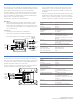
Contact Relay Module
E-RLY
The E-RLY provides one Form C dry relay contact. It can also be
configured to provide polarity reversal of its output. The E-RLY can
be used to control external appliances or shut down equipment.
The E-RLY is wired according to its operation. It is configured to op-
erate as a relay nonsilence device type, and can function as either a
control relay or polarity reversal relay, depending on how it is wired.
Control relay function: Provides one Form C dry relay contact.
Polarity reversal relay function: Provides polarity reversal of its
output.
Note: Additional device types are available through front panel
programming or the configuration utility. Refer to applicable control
panel technical reference manual.
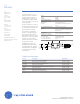
TB2
TB1
From
previous
device
SLC in (+)
SLC out (+)
SLC in
SLC out
To next
device
Normally open
Common
Not used
Normally closed
SLC
(+)
(NC)
(NO)
(C)
( )
( )
( )