
Cut Sheet

Data Sheet S85001-0611 Issue 1
Not to be used for installation purposes. Page 4 of 6
Dual Input Waterflow, Supervisory Module
E-IDCWS
contact initiating devices. When the NO input contact of an
initiating device is closed, a supervisory signal is sent to the
control panel and the supervisory condition is not latched at
the module.
Latching: Configures the module for normally open dry contact
initiating devices. When the NO input contact of an initiating
device is closed, a supervisory signal is sent to the control pan-
el and the supervisory condition is not latched at the module.
•
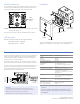
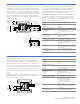
The E-IDCWS connects normally open waterflow alarm and supervi-
sory initiating device circuits (IDCs) to the Edwards Signaling control
panel. The E-IDCWS is designed for Class B circuit operation.
The device address is set using the two rotary switches located on
the front of the module. Two consecutive addresses are required.
The second address is automatically assigned one number higher
that the value set on the rotary switches.
The E-IDCWS can operate in the following modes:
Waterflow
Alarm latching delayed: Configures the module for use with
only nonretarded waterflow alarm switches. When the NO
input contact of an initiating device is closed, an alarm is sent
to the control panel, which after a 16 second time delay, gener-
ates an alarm signal.
Supervisory
Supervisory active nonlatching US marketplace
Supervisory active latching Canadian marketplace
Nonlatching: Configures the module for normally open dry
•
•
•
•
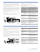
SLC Fault Isolator Module
E-ISO
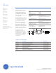
The E-ISO protects a Class A SLC from total collapse due to wire-to-
wire short circuits. The module monitors line voltages and opens the
SLC when a short is detected. A short is isolated between the two
modules located electrically closest to the short.
The device address is set using the two rotary switches located on
the front of the module. One device address is required.
From
previous
device
To next
device
TB2
SLC OUT
SLC IN
(+)
(+)
( )
( )
( )
( )
Communication line voltage Maximum 20 V peak-to-peak
Current
Standby
Activated
175 μA
200 μA
Ground fault impedance 10 k ohm
Maximum circuit resistance
between isolators
6 ohm
Operating environment
Temperature
Humidity
32 to 120°F (0 to 49°C)
0 to 93% RH, noncondensing at 90°F
(32°C)
Storage temperature range –4 to 140°F (–20 to 60°C)
Compatible electrical boxes North American 4 inch square x 2-1/2
in. (64 mm) deep 2 gang box
Standard 4 in. square box 1-1/2 in. (38
mm) deep
Wire size 12, 14, 16, or 18 AWG wire (2.5, 1.5, 1.0,
or 0.75 sq. mm) (Sizes 16 and 18 AWG
are preferred)
Module address 01 to 64 (64 point control panel)
01 to 127 (127 point control panel)
Typical NO
Waterflow Switch
47
EOLR
k Ohm
47
EOLR
k Ohm
SUP.
Style B (Class B)
W/FLOW
Typical NO
Supervisory/
Tamper Switch
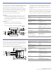
TB2 TB1
(+)
(+)
SLC
(+)
( )
( )
( )
From
previous
device
To next
device
SLC out (+)
SLC out
SLC in
SLC in (+)
( )
( )
Communication line voltage Maximum 20 V peak-to-peak
Current
Standby
Activated
550 μA
725μA
Ground fault impedance 10 k ohm
Operating environment
Temperature
Humidity
32 to 120°F (0 to 49°C)
0 to 93% RH
Storage temperature range –4 to 140°F (–20 to 60°C)
Compatible electrical boxes North American 4 inch square x 2-1/2
in. (64 mm) deep 2 gang box
Standard 4 in. square box 1-1/2 in. (38
mm) deep
Wire size 12, 14, 16, or 18 AWG wire (2.5, 1.5, 1.0,
or 0.75 sq. mm) (Sizes 16 and 18 AWG
are preferred)
Device address 01 to 63 (64 point control panel)
01 to 126 (127 point control panel)
Initiating device circuit (IDC)
EOL resistor value
Max. circuit resistance
Max. circuit capacitance
47 kΩ, (P/N: EOL-47)
50 Ω (25 Ω per wire)
0.1 μF