
Cut Sheet

Data Sheet S85001-0611 Issue 1
Not to be used for installation purposes. Page 2 of 6
Warning
This module will not operate without electrical power. As fires
frequently cause power interruption, you should discuss further
safeguards with your local fire protection specialist.
This module does not support conventional smoke detectors.
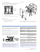
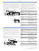
Module Addressing
Use a screwdriver to adjust the two rotary switches on the front of
the module. Set the TENS rotary switch (0 through 12) for the 10s
digit and the ONES rotary switch for the 0 through 9 digit.
Insert
screwdriver
here
Example: device address 21, set TENS rotary switch to 2 and set the
ONES rotary switch to 1.
Refer to the Specifications Table for available address numbers.
LED operation
Modules provide a bicolor LED for status indication.
Flashing Green LED Normal
Flashing Red LED Active
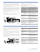
Installation
Screw
4-24
screws
Module
Wall plate
Compatible
electrical box
Mount in a North American 4 inch square x 2-1/2 in. (64 mm) deep 2
gang box or a standard 4 in. square box 1-1/2 in. (38 mm) deep.
Caution
Wire in accordance with NFPA 72 and CAN/ULC-S524.
Be sure to observe the polarity of the wires as shown in
the diagram.
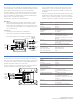
Class A Single Input Module
E-IDC1A
The Class A Single Input Module is used to connect a normally open,
alarm, supervisory, or monitor type dry contact initiating device
circuit (IDC) to the Edwards Signaling control panel. The module is
designed for Class A circuit operation.
The module's device address is set using the two rotary switches
located on the front of the module. One device address is required.
The device can be preset for alarm or supervisory operation using
the slide switch located on the front of the module. The module
can also be configured for other device types through front panel
programming or the configuration utility.
TB2
TB1
(+)
(+)
(+)
(+)
RETURN
IDC
Typical NO
Initiating device
Style D Class A
To next
device
From
previous
device
SLC out
SLC out
SLC in
SLC in
SLC
(+)
( )
( )
( )
( )
( )
Communication line voltage Maximum 20 V peak-to-peak
Current
Standby
Activated
400 μA
500 μA
Ground fault impedance 10 k ohm
Operating environment
Temperature
Humidity
32 to 120°F (0 to 49°C)
0 to 93% RH, noncondensing at 90°F
(32°C)
Storage temperature range –4 to 140°F (–20 to 60°C)
Compatible electrical boxes North American 4 inch square x 2-1/2
in. (64 mm) deep 2 gang box
Standard 4 in. square box 1-1/2 in. (38
mm) deep box
Wire size 12, 14, 16, or 18 AWG wire (2.5, 1.5, 1.0,
or 0.75 sq. mm) (Sizes 16 and 18 AWG
are preferred)
Device address 01 to 64 (64 point control panel)
01 to 127 (127 point control panel)
Initiating device circuit (IDC)
Max. circuit resistance
Max. circuit capacitance
50 Ω (25 Ω per wire)
0.1 μF