
Instruction Manual


P/N 3100125 ISSUE 3 PAGE 10
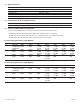
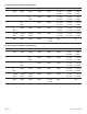
SW1 SW2 SW3 SW4 SW5 SW6 SW7 SW8
BAUD RATE - 125 Kbps 0 0
BAUD RATE - 250 Kbps 0 1
BAUD RATE - 500 Kbps 1 0
BAUD RATE - 125 Kbps 1 1
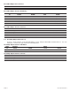
MAC ID 0 000000
MAC ID 1 000001
MAC ID 2 000010
MAC ID 3 000011
MAC ID 4 000100
MAC ID 5 000101
MAC ID 6 000110
MAC ID 7 000111
MAC ID 8 001000
MAC ID 9 001001
MAC ID 10 (0x0A) 001010
MAC ID 11 (0x0B) 001011
MAC ID 12 (0x0C) 001100
MAC ID 13 (0x0D) 001101
MAC ID 14 (0x0E) 001110
MAC ID 15 (0x0F) 001111
MAC ID 16 (0x10) 010000
1. Make DeviceNet connections to the 5 position female terminal block plug as indicated in the below table. The 5
DeviceNet bus terminals are silkscreened near the terminals on the printed circuit board. Make connections as
follows:
WARNING
To avoid electrical shock hazards, do not connect
wires when power is applied.
Pin 5 V + Red Wire
Pin 4 CAN_H White Wire
Pin 3 Drain Bare Wire
Pin 2 CAN_L Blue Wire
Pin 1 V - Black Wire
Pin 1 (+) + 24V DC Red Wire
Pin 2 (-) - 24V DC Black Wire
2. A two (2) position screw terminal is provided to connect either separate 24V DC or 120V AC (depending on version
-G1 (24V DC) or -N5 (120V AC) light source operating power to the Triliptical DeviceNet Stackable Beacon. The
terminals for the 24V DC unit are labeled as "+" and "-". Polarity is not important for the 120V AC unit. Make
connections as follows:
Pin 1 120V AC Black Wire
Pin 2 120V AC White Wire
3. For the 24V DC unit only, if it is desired to power the light sources from DeviceNet power, jumper (V+) and (V-) on
the 5 position DeviceNet terminal block to (+) and (-) respectively on the 2 position screw terminal.
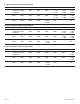
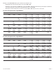
Set DIPSWITCH S1 for the BAUD RATE and MAC ID required as follows:
Note the legend on the dipswitch for the sense of 0 and 1 (0 = OFF and 1 = ON)
or