ErP Announcement Product: Internet Camera (IP CAM) Purpose: 24 hours surveillance and transfer the picture for safety and health of intended use. Detail description: Health purpose: User can pass through the internet (from everywhere) to control the product (IP CAM). To watch and listen the people who needs to be cared in house and automatically send e-mail and phone to warn you and ask your attention. The product also provides a record function to keep all images and voice information for record.
Table of Contents Chapter I Product Introduction…………………………………………………………………….7 1-1 Package Contents……………………………………………………...……………………...7 1-2 System Requirements……………………………………………………...………………..8 1-3 Highlights of the DDNS-Free Outdoor IP Camera…………………………………..........9 1-4 Familiar with the IC-9000……………………………………………………......................10 1-5 Install the IC-9000…………………………………………………………………………….11 1-5-1 Hardware Installation………………………………………………………………………11 1-5-2 Software Installation………………………………………………………..............
-3-3 Rename……………………………………………………………………………………..47 4-3-4 Delete………………………………………………………………………………………..48 4-3-5 Refresh Status……………………………………………………………………………...48 4-3-6 Camera Adjustment………………………………………………………………………..49 4-3-7 Play on Selected Window…………………………………………………………………50 4-3-8 ID / Password Settings…………………………………………………….......................50 4-3-9 Video Settings………………………………………………………………………………51 4-3-9-1 Quality Function Tab…………………………………………………….......................
6-3-2 General Settings……………………………………………………………………………92 6-3-2-1 ‘General’ tab……………………………………………………………………………...92 6-3-2-2 ‘E-Mail Setting’ tab……………………………………………………………………….94 6-3-2-3 Security…………………………………………………………………………………...96 6-3-2-4 About…………………………………………………………………………………….98 6-4 Change Display Layout…………………………………………………….......................99 6-5 Full-screen Modes………………………………………………………………………….102 6-6 Scan………………………………………………………………………….......................
Copyright by Edimax Technology Co, LTD. all rights reserved. No part of this publication may be reproduced, transmitted, transcribed, stored in a retrieval system, or translated into any language or computer language, in any form or by any means, electronic, mechanical, magnetic, optical, chemical, manual or otherwise, without the prior written permission of this company.
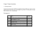
Chapter I Product Introduction 1-1 Package Contents Thank you for purchasing this DDNS-Free Outdoor IP Camera! Before you start to use this product, please check every item in the package. If any of them is missing, please ask your dealer of purchase for a new package. Packaging List Item No. Name Quantity 1 DDNS-Free Outdoor IP Camera 1 2 Power Adapter 12V 1.
1-2 System Requirements CPU: Pentium 4 (or equivalent AMD) 1.
1-3 Highlights of the DDNS-Free Outdoor IP Camera Thanks again for choosing this DDNS-Free Outdoor IP Camera. The IC-9000 is designed with the User-friendly concept. You can install the IP Camera easily on your home network and then access the IP Camera anywhere in the world with the video management utility. No need to set complicated DNS name or change the router configuration. It just a plug & play.
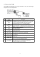
1-4 Familiar with the IC-9000 The IC-9000 is designed to be very easy to install and use. First, let’s see the major components of the IP CAM products. Item No. Name 1 Ethernet Indication LED (blue) 2 Status Indication LED (red) 3 Lens 4 IR LEDs 5 Light Sensor 6 Ethernet Jack 7 Digital Input Terminal Block 8 Power Jack 9 Reset Button Description Indicates if the Ethernet link is ok and packet traffic is sending/receiving.
1-5 Install the IC-9000 There are only three things that you need to do to see the video from the IC-9000: 1. Connect the IP CAM to the home/office network. 2. Install the CamView software on the notebook/PC. 3. Key in the ID/password of the IP CAM(from the ID/Password card) on the CamView, and then you can see the video. 1-5-1 Hardware Installation Please follow the following instructions to set up the IC-9000: 1.
1-5-2 Software Installation 1. Before installing CamView software on your PC or laptop, please make sure you have correctly installed the IC-9000. It’s highly recommended to close other Windows applications to prevent the installation from any possbile confliction. 2. Please insert the installation CD into the CD-ROM drive in your notebook or personal computer (must be running Microsoft Windows OS). 3. Execute the program CamView on the disk.
Chapter II Start Using the DDNS-Free Outdoor IP Camera 2-1 Use CamView Software to See the Video Following figure is the running window of the CamView program. If the computer and the IC-9000 is connected to the same network, the ID of the IC-9000 will be displayed in the “Auto Search” list. If you have more than 1 piece of the IC-9000, you can double click the “Auto Search” to search all the connected the IC-9000s any time.
2-2 Seeing the Video in a Remote Location After the IC-9000 is installed and you can see the video from the CamView software in the local network, it’s very easy to see the video in a remote location. All you need to do is add a camera item in the “CameraList” 14folder of the CamView software, key in the ID and Password of the IC-9000 (from the ID/Password card). And then double click this camera item. You will then see the Camera video immediately. No further NAT/router setting modifications are needed.
Chapter III Start Using Web Configuration Page You can login into the web configuration page by directly key-in the IP address of the IP CAM or right-click the searched IP CAM in the “Auto Search”15list of the CamView software and click the “Web Configure” to open the login window of the IP CAM. The default login account is “admin”, leave the Password field empty.
3-1 Information The first page of the web configuration of the IP CAM is the information page. You can see the model name/firmware version, IP CAM ID, registration status, network type and current video settings (bandwidth & resolution) in this page. The IP CAM can be viewed remotely by the CamView software only when the IP CAM is registered. If this IP CAM is not registered, please check the Ethernet wiring of your network environment.
3-2 Video Display This display page allows you to view the video display of the IP camera. For the first time use of this display on a computer, an activeX component will be automatically downloaded into the browser. This could take some time, depends on the internet speed. The component is downloaded from a public domain, so that the computer must be connected to the Internet. If you want to modify the video display screen size, please refer to section 3-7 for more details.
3-3 Network The Network page allows you to modify the network settings of the wired Ethernet. The default settings use DHCP to obtain an IP address automatically. In most of the home and office network environment, there is a DHCP server running. In this situation, by using this default settings, the IP CAM can work immediately in most of the time. If the Ethernet cable is unplugged, the IP CAM will lose connection.
3-4 Advanced Network In some special situation, your network environment only provides PPPoE connection (ADSL service), there is no NAT/router available. You will then need to set the PPPoE settings in the “Advanced Network”20page. Only the PPPoE username and password are needed to let PPPoE work. After the ”Save&Apply” button is pressed, the PPPoE function will work immediately. You can check the ”Registration status” in the “Information” page to see if the IP CAM is registered using the PPPoE connection.
3-5 Video Settings The IP CAM is designed to provide high quality video for viewing from CamView software. In this page, you can modify some settings related to the video viewing: 1. Password (play video) - This is the password needed for viewing the video from the CamView software. Together with the IP CAM ID, you can view the video of this IP CAM anywhere in the world through the Internet. 2. Internet speed - This is the Internet bandwidth of your network environment.
clearance. The default value of this setting is “high”. 10. Video color - Choose between “colored” and “black&white”. 11. Outdoor/Indoor video - For better video display quality, modify this setting when taking indoor or outdoor video. The default setting is “Outdoor video”, in most cases, this is also ok for indoor usage. Under some special cases, there could be some strip lines on the video display when the IP camera is taking indoor video.
3-6 3GPP/RTSP Settings The IP CAM is able to be viewed from a 3G mobile phone, for detailed settings on the 3G mobile phone, please refer to Appendix F. Users can disable the 3G mobile access ability in this page. After the 3GPP/RTSP feature is disabled, no 3G mobile phone is allowed to access the video of the IP camera. When this is disabled, the rtsp stream with MPEG2 audio is still working, please refer to Appendix F for more details about rtsp stream with MPEG2 audio.
3-7 Night Mode Control The IP Cam is able to work both in day time and night time. There are some IR LEDs that can let the IP camera see the objects in the night time. Users can adjust the numbers of the IR LEDs according to the view sight distance during night mode to get the best night mode vision. The night mode status is also displayed. This night mode control page is to control when the time the IR LEDs will be on. There are three ways to control the night mode ( IR LEDs ) : 1.
3-8 Email/FTP Alarm The IP CAM provides the Email/ftp function, you can enable or schedule the Email/ftp ability in this page, the IP CAM will then send out an email with a jpeg picture attached in the email and/or send out the jpeg picture file to a ftp server. The related settings are explained below: 1. Email/FTP trigger – choose between “motion”, “D/I”, “schedule” and “disable” A. B.
email message. The SMTP server and username/password account are only for transfer the email message to the “Email recipient”, the “Email recipient” could be on another email server or any reachable email address. The username and password fields could be left empty if no authentication is needed for the SMTP server. 7. SMTP server test – after the settings are filled, you could press “SMTP server test” to check if all the settings are correct. 8.
3-9 DI/DO Settings The IP camera provides DI alarm detection function. The related settings are explained below: 1. Digital input – can select the normal status of the digital input as either open circuit or closed circuit. The current status is also displayed. An active status could trigger the email/ftp or the NAS/SD card recording by setting the scheduling.
3-10 NAS Settings The IP Camera provides the recording of the video files into a standard NAS (Network Access Storage) device. The IP camera connects to the NAS device using the standard LMX_NS/CIFS/SSN protocols that are the same as the Microsoft Windows network neighborhood protocols. This makes the IP camera easily record the video files to some of the standard NAS devices* in the market.
In the Microsoft Windows environment, you can access to the NAS device by keying the URL address \\”NAS name”\”shared folder name” or \\”NAS IP address”\”shared folder name” in the windows Internet Explorer, and then key in the “NAS access account” and “NAS access password” to the prompted login window. The video files are recorded under the subfolder IPCamRecordFiles/Recording/ID-ID, where ID is the ID of this IP camera. All the recorded files are with the name of hhmmss.
3-11 Scheduling The IP Camera provides the scheduling function for the motion detection triggered email/ftp sending and/or the NAS recording with the individual parameters set in the . “Email/ftp alarm” settings and the “NAS settings” page. Totally 12 schedule list items are allowed. There is no conflict check for the scheduling, it means that the scheduling time could be overlapped, and the IP camera will do all the scheduled events during the overlapped time period.
3-12 Date/Time The IP CAM can synchronize the date/time with the universally available time server (for example stdtime.gov.tw) through NTP protocol. The date/time will then be corrected with the time server anytime when the Internet is connected. Users can choose the different TimeZone of their areas to display the correct time. For some TimeZone areas, the “Daylight Saving Time” could be enabled or disabled.
3-13 Admin In this page, you can modify the web login account. With this account, you can login to the IP CAM and do any modifications. The default account is “admin” without password. If the login account is forgotten, you can reset the IP CAM to the factory default settings by following the steps in section 3-17 and login with the “admin” account. Please be noticed that this account is different from the video play password in the “Video settings” page.
3-14 Upgrade If there is some new firmware available for this IP CAM, you can upgrade the firmware via this page. A status message about the percentage done in the upgrade procedure is displayed. Please be noticed that during the upgrade procedure, do not power off the IP CAM, otherwise, the IP CAM could probably enter into the safe mode (section 3-16). After the upgrade procedure is finished, the system will restart automatically.
3-15 Reboot You can restart the IP CAM manually on this page. All the connected video viewing users will be disconnected.
3-16 Safe Mode If by some abnormal operation, for example, powered off during the critical point of the upgrade procedure, the IP CAM will enter into the safe mode. In this mode, you will see the following “Safe mode” page when login into this IP CAM. Please do the upgrade operation immediately to recover the system. On this safe mode, the IP CAM cannot display the video on the CamView software, but you can still find this IP CAM on the “Auto search” list.
3-17 Set to Factory Default For some reason, for example you forgot the web login password, you may want to set the IP CAM to the factory default settings. The only thing you need to do is pressing the “reset” button on the cable for more than 4 seconds and release it, do this when the IP CAM is powered on. The IP CAM will reset to the factory default settings and restart automatically.
Chapter IV Start Using CamView 4-1 Install CamView Program 1. Please close other windows applications before proceeding. 2. Insert the installation CD into your CD-ROM drive and find the CamViewInstaller.exe. Double click it to start the installation process and you will see the “Welcome” window. Click 3. If you are uncertain if the Framework 2.0 is already installed on your PC, please check .NET Framework 2.0. Click to proceed installation.
4. Click to proceed 5. Make a selection and click lick 6. Click to proceed. to proceed.
7. Click to exit. CamView installation now is completed.
4-2 Startup and the Layout of CamView 4-2-1 Startup CamView You can startup CamView from either Start Programs CamView or the shortcut of CamView on the windows desktop.
4-2-3 Display Mode CamView supports 10 display modes. By pressing each mode, you can have a different live view display.
4-3 Managing CamView Camera IP cameras Right click the “Camera List” .You can add a new IP cam, create a new folder, rename the IP cam or the folder, and delete any IP cams or any folder.
4-3-1 New Camera Users can add a new camera to the list by entering IP cam ID and password. Users can also name the IP cam.
4-3-2 New Folder Users can group IP cams by creating a new folder. Right click on the “Camera List”.
4-3-3 Rename You can rename the folder.
4-3-4 Delete You can delete the folder.
4-3-6 Camera Adjustment By right clicking on a green light status IP cam, you can access the video display, do ID and password settings, adjust video settings, upgrade firmware, and delete from the list. Function List Right click Green status Camera Note: Camera status must be green in order to access function list.
4-3-7 Play on Selected Window Click it Video shows up here 4-3-8 ID / Password Settings Edit Camera Name, ID, and Password. Click OK to activate new setting.
4-3-9 Video Settings Click Update for the changes to take effect. All the settings are categorized according to its function.
4-3-9-1 Quality Function Tab Bandwidth Available selections are from 64K to 1.5M. Appropriate bandwidth setting must match the camera physical site internet uploading bandwidth. Higher bandwidth contributes better picture quality. Video Setting If you check the box of select the best resolution and frame rate automatically, the camera will automatically adjust the most suitable video setting in Resolution and Frame Rate Resolution: higher resolution you set, bigger image you get.
Disable or enable the microphone. When you enable the Mic., the user who monitors the image can hear the sounds. Video Flip This function is only available for the Pan Tilt type of camera to flip the image.
4-3-9-3 Control Function Tab Check the box to allow user remotely controls the motors for Pan and Tilt. (Only available for the Pan/Tilt type of camera) Status of LED Control User can control the behavior of the status LED. Motion Detection Sensitivity The level of how sensitive the camera is in terms of the motion detection. 4-3-9-4 Camera Info Tab Show the IP camera information and firmware version.
4-3-10 3GPP Setting To allow 3GPP connections from mobile phones, user has to enable it. Bandwidth The bandwidth setting for 3GPP connection from 32k to 256K. Video Setting Check the box to make the camera determine the best combination of the resolution and frame rate according to the given bandwidth.
4-3-11 Firmware Upgrade The firmware upgrade function is designed for trouble shooting and technical assistance remotely.
4-4 Displayed Video Control Use mouse to select displayed window. Right click to see various functions Double click information bar to make it full window display Snapshot button Press it to snapshot Record Status Light Black: Non recording Red: Continuous recording Green: MD recording Double click displayed video to make it full screen display Full Window: Choose it to display video in full window. Users can also double click the information bar to display in full window.
Recording status turns into green Properties: Show current IP cam’s frame rate, consuming bandwidth, and camera physical site time. Snapshot & Continuous Recording Click to do continuous recording. Status light becomes red. Click to take snapshot.
Swap Function: This function is available only in 6, 13, 21 window display modes. Press swap button to move the minor window video to/from main window. Press Swap button to move minor window display video to or from main window display video. Auto Search: Auto search is a function that searches for all IP Cameras on your LAN (Local Area Network). At the very beginning of CamView startups, CamView automatically does the auto search. To do auto search manually, double click on the “Auto Search” folder.
Auto Search List: List all the found Cam IDs within this LAN. Web configure: Click to open I.E. browser for further configuring this IP Cam. Move your mouse over Cam ID 001006123 to see its IP address. IP Cam Online Status Indication: There is an IP Cam icon in front of the Camera Name which indicates the online status of that IP Camera. RED IP cam is off line, not connecting to internet. GREEN IP is on connected to internet.
Panel will be activated as below: Pan Scan: make the Pan Tilt Dome move left and right Tilt Scan: make the Pan Tilt dome up and down Speed: the speed of Pan Tilt Dome has 3 level of speed (3 is the fastest, 1 is the slowest) : Move Up : Move Down : Move Right : Move Left : Move back to home Patrol: User can have 1 set of Patrol and 5 points for each Patrol. To set each point for the patrol, User can use the direction arrow in blue to set each point the user want to stop in a patrol.
Preset: This function will be activated after any PTZ Dome connect with video server Zoom in & out: This function will be activated after any analog PTZ Dome Camera connect to IP video server 62
4-5 Camview Software Functions CamView Function Bar. 4-5-1 Setting Click Setting and get into the Setting Function menu. Directories Settings: to set the directory path for the Recording and Snapshot Where to save the recording files. Click to open the recording folder. Click to change the path Where to save the snapshot files. Recording options Click to save the setting 63 Available disk space of current selected hard drive.
Startup Options: Determine the camera state at startup Automatically start CamView when Windows starts: When Microsoft Windows starts, CamView will start running automatically. Restore the last time playing/running state: Restore the state of each video window to what it was before CamView closed.
4-5-2 CamPlay Click CamPlay to start it for playback. 4-5-3 Scheduling Click Scheduling to configure scheduled recording/playing. Schedule the time for each channel to be used and recorded by certain camera Camera: The information of the camera to be connected. You can either double click on one of the listed cameras or drag the camera off the Camera field to import the settings. Of course, manually key in the Name, CamID and password is fine as well. Mode: There are 3 modes available to choose from: 1.
Continuous Recording: Window number. Enable/disable the scheduling for current window number. The schedule mode The start/end time (for play only/continuous recording mode) Enter the information of the camera to be connected.
Periodic Recording: The schedule mode (Periodic recording) The period of time for this schedule to be valid Arrange the days of week for camera to record Determine the priority between “current camera” and “scheduled camera” Recording/Playing Conflict: When the schedule time is reached, the program needs to determine either to run the scheduled camera or keep the currently used camera for this window. Choosing “Record as scheduled”, CamView connects to the scheduled camera.
4-5-4 Language Click Language button to change the language settings. Right now, CamView supports 19 languages shown as following picture: 4-5-5 All Functions Any of following functions applies to all the channels in current layout only Record all: start/enable recording. Snapshot all: Take snapshot. Play all: Start playing. Pause all: Pause. Disconnect all: Stop playing.
4-6 Uninstall CamView There are two ways to invoke the CamView uninstaller. 1. Uninstall from the start menu Start CamView Uninstall CamView 2.
Chapter V Start Using CamPlay There are two ways to start CamPlay for playback the recorded files or view the snapshot files. One way is clicking the CamPlay button on the tool bar of CamView. Click the CamPlay button. Another is double click on the Camplay shortcut on your Windows desktop.
5-1 CamPlay File Tree Recorded videos and snapshots are separated as shown: Name / ID of cameras Date: yyyy/MM/dd Time: hh/mm/ss The folder structure is: Camera (Name-ID) -- Date -- File (time) 71
5-2 CamPlay Functions Refresh file tree Directory Language Refresh File Tree: Click it to refresh the file trees especially after CamView is done with recording or snapshot. Directory: Click to get into the directory settins dialog for recording and snapshot. Click the settings.
5-3 Language Right now, CamPlay supports 18 languages as following: English, Chinese, Japanese, French, Germany, Italian, Spanish, Hungarian, Turkish, Czech, Hebrew, Indian, and Finnish.
5-5 Convert to “AVI” Transcoding to avi format is supported. Simply right click on the file you want to transcode and select “Covnert to .avi”. Wait for a while and the transcoded file will be saved in the same folder with the original file. Select “Open folder” to browse all the files recorded in the same day from the same camera.
5-6 Playback Function Bar To playback the recorded file, you can either double click on it or drag it to the video window directly. To view the snapshot file, simply double click on it and the snapshot will be opened by the default viewer of your computer. Drag time bar to select target playback video time Pause / Resume Play Fast Forward Mute / Un-Mute Stop Slow Forward Take Snapshot Zoom In / Out 5-6-1 Snapshot The snapshots you taken within CamPlay are saved in SNAPSHOT_DIRECTORY\CamPlay\date\.
Chapter VI Start Surveillance Software If you have IC-9000 as well as other Edimax IP cameras, you are suggested to install surveillance software for viewing all IP cameras you own. 6-1 Installing IP Camera Surveillance Software The IP camera surveillance software provides various functions like video recording, after this software is installed, you can use your IP camera to safeguard your property. Please follow the following instructions to install the surveillance software. 1.
3. If you need installation program to create a desktop icon or a quick launch icon for you, click all items you need here, then click ‘Next’ to continue. 4. Here lists all options you chose in previous steps, if everything’s correct, click ‘Install’ to start installing procedure, or click ‘Back’ to go back to previous step to modify installing settings.
5. The installing procedure will take some time, please be patient. 6. When you see this window, it means the software installing procedure is complete. Please click ‘Finish’ to finish the procedure (IP camera surveillance software will start after you click ‘Finish’ button, if you want to start it later, uncheck ‘Launch IPCam Surveillance Software’ box).
6-2 Using IP camera Surveillance Software You can click ‘IPCam Surveillance Software’ icon from desktop, quick launch bar, or start menu to start the IP camera surveillance software. Before you start: IP camera surveillance software will only work when your monitor’s resolution is ‘1024 x 768’. Please change the resolution before you use IP camera surveillance software, or it won’t start.
You can put the mouse cursor on a certain component and see its button name, and here’re detailed descriptions of all buttons: Item Description Video displaying The image of all connected cameras will be displayed here. area Language Select a language from this dropdown menu to change display language. Display layout Change camera image display layout (Click a layout icon to change camera display layout). There are 8 kinds of available display layouts.
Close window Terminates IP camera surveillance software. (stop surveillance) Minimize window Minimizes IP camera surveillance software window. Video displaying Displays the image of all cameras by the display layout you area selected.
6-3 Configure IP camera Surveillance urveillance Software 6-3-1 Configure Cameras Before you use this IP camera surveillance software, you must configure the camera(s) you wish to connect.
6-3-1-1 ‘Camera’ tab In this tab you can configure all cameras you wish to connect. Up to 16 cameras can be connected simultaneously: Here are the descriptions of all setting items: Item Description Channel Select the channel number you wish to set. Camera Search All cameras found on your local network will be displayed in ‘Camera Search’ box.
IP* Input the IP address of camera. Username* Input the user name of camera. Web Port* Input the web port of the camera. By default it’s ‘80’. Password Input the password of camera. Default value is ‘1234’. You should change the password if you changed the password of selected camera. Video Format** Select the video encoding format of this camera (MJPEG or MPEG4). Reset OK Cancel Clear all fields in ‘Camera Configuration’ section. Save settings in this tab. Discard all settings in this tab.
6-3-1-2 Schedule Recording In this tab, you can setup scheduled video recording, so you can record the video captured by all cameras you have by a pre-defined schedule.
Here are the descriptions of all setting items: Item Channel One Time Schedules Description Select the channel number you wish to set. You can specify the one-time schedule for selected camera; this schedule will be executed once only. Click this button and a new window will appear: New (One Time Schedules) Please specify the time duration of this one-time schedule (the date and time of ‘From’ and ‘To’), then click ‘OK’ to save settings.
Edit Delete OK Cancel You can modify a scheduled recording item. Select a schedule in ‘One Time Schedules’ list, and click ‘Edit’ button to edit the start and end time of this schedule. Delete a selected schedule item. Save settings in this tab. Discard all settings in this tab.
6-3-1-3 Audio For cameras that support audio, you can use this tab to decide if you wish to hear the audio captured by selected camera. Here are the descriptions of all setting items: Item Channel Description Select the channel number you wish to set. Mute Audio Check this box and the IP camera surveillance software will not play the audio captured by this camera. Record Video Only Check this box and the IP camera surveillance software will not record the audio captured by this camera.
6-3-1-4 Motion Record With this function activated, only motions captured by the camera will be recorded, so you don’t have to waste hard disk storage space on images you don’t need to pay attention to. WARNING: For applications that security is highly concerned, it’s not recommended to use this function since some tiny changes you may need to know may not be able to trigger the camera and the camera will not start recording.
OK Cancel Save settings in this tab. Discard all settings in this tab.
6-3-2 General Settings You can set system-wide settings of this IP camera surveillance software in this menu. 6-3-2-1 ‘General’ tab All general settings like file storage directory and recording spaces can be set here. Here are the descriptions of all setting items: Item Description Data Directory Set the directory (folder) you wish to store the recorded video and captured image. You can click ‘Browse’ button to pick a directory in your hard disk. Free Recording Displays remaining storage space.
OK Cancel Save settings in this tab. Discard all settings in this tab.
6-3-2-2 ‘E-Mail Setting’ tab If you want to use motion detection function and wish to get an email that contains the image captured by the camera, please setup your email related parameters here first. Here are the descriptions of all setting items: Item Description E-Mail Subject Specify the subject of sending email. Recipient E-Mail Address Here lists all email addresses you set. Click this button and you’ll be prompted to input the email address. Click ‘OK’ to save changes.
Sender E-Mail Specify the email address of email sender. Address Specify the IP address or host name of the SMTP server you wish to use. For most of ISPs they will only allow its subscriber to use their SMTP Server SMTP server, if you don’t know which SMTP server you should use, please refer to the setting of your email software or ask your ISP / network administrator. SMTP port Specify the port number of the SMTP server you wish to use here. By default (and the setting of most of SMTP servers) it’s ‘25’.
6-3-2-3 Security If you don’t want other people to access this IP camera surveillance software, you can set a password to protect it. You’ll need to input the password every time you wish to use this IP camera surveillance software: To set password, please use ‘Security’ tab in ‘General Options’ menu: Here are the descriptions of all setting items: Item Enable Description Requires password authentication when this software starts.
Disable Password Password authentication is not required when this software starts. Input the password you wish to use here. Confirm Password Input the password you wish to use here again.
6-3-2-4 About This tab shows the version number of the IP camera surveillance software you’re using.
6-4 Change Display Layout This IP camera surveillance software provides 8 kinds of display layout: Every layout displays different number of camera and camera arrangement, you can click the icon that presents a specific kind of layout, and the video displaying area will change accordingly. Displays the video of 1 camera only. Layout style 1: 1 Camera only Displays the video of up to 4 cameras.
Displays the video of up to 6 cameras. Layout style 3: 6 Cameras Displays the video of up to 8 cameras. Layout style 4: 8 Cameras Displays the video of up to 9 cameras. Layout style 5: 9 Cameras Displays the video of up to 10 cameras. Layout style 6: 10 Cameras Displays the video of up to 13 cameras.
Displays the video of up to 16 cameras.
6-5 Full-screen Modes If you want to use all available spaces on your monitor to display surveillance image, you can click ‘Full Screen’ button to switch display mode to full-screen mode. To exit full-screen mode, press ‘ESC’ key.
6-6 Scan If you have more than one camera configured, and you wish to switch the displaying image between cameras, you can click ‘Scan’ button to switch between all configured cameras. NOTE: If a camera is configured but disconnected, it will still be displayed in a scan sequence (you’ll ll see nothing and you’ll see ‘Disconnected’’ text displayed at the upper-left left corner of display image).
6-7 Zoom-in / Zoom-out For cameras that support zoom-in / zoom-out function, you can use this function to see more objects that fall in the scope of camera’s view, or enlarge the image size of a certain object to see its detail.
6-8 PTZ For cameras that support pan - tilt function, you can change the position that camera points to, to see different places that fall in the scope of camera’s view. Please select a camera in video displaying area by clicking on its image, and then click the directions you wish the camera to move to (total 8 directions available). Click ‘Home’ button ( ) to return to camera’s home (default) position.
6-9 Snapshot You can take a snapshot of selected camera and save it to ‘Snapshot’ sub-folder of pre-defined data directory. Click snapshot button once to take a snapshot; you can take as much snapshot as you want before hard disk is full.
6-11 Video Playback You can playback all recorded video by clicking this button. A new window will appear: You have to search the video file before you can play it. There are two kinds of video search: Time Search (search all videos file that falls in a specific period of time) and Motion Search (search all videos recorded by motion detection function and falls in a specific period of time).
Appendix A. Features Easily access the camera from anywhere in the world via the ID/password No complicated NAT/router settings needed. Free video management software - CamView program accompanied for easy access and multi-camera management. 3GPP/ISMA support. Dual video streaming with separate frame rate/resolution/bandwidth settings for PC and mobile. IR led control – support automatic, manual and scheduled modes. But only can see black & white video when IR led is on.
Appendix B. Specifications Models DDNS-Fee Outdoor IP Camera with Night Vision Power DC 12V, 1A Processors RISC CPU, hardware video processing and compression. Network interface Ethernet 10BaseT/100BaseTX, Auto-MDIX, RJ-45 Image sensor RGB VGA 1/4 inch CMOS Automatic exposure control, automatic white balance, automatic gain control, automatic brightness control. Light sensitivity 0.2 Lux ( IR led off ) 0 Lux (with 30 meters IR leds on) Automatically turn on the IR led in low light environment.
maintenance Video management software-CamView for video access and multi-camera management Firmware upgrades via FTP Minimum Web Built-in web server for standard web browser access browsing and Pentium 4 CPU 1.0 GHz or higher, or equivalent AMD management 1GB RAM software requirements Supported protocols IPv4, HTTP, TCP, ICMP, RTSP, RTP, UDP, IGMP, RTCP, SMTP, SNTP, FTP, DHCP, UPnP, ARP, DNS, PPPoE, etc.
Appendix C. Maximum Allowed Video Users The maximum allowed video users for a single IP Cam at the same time is dependent on the video settings including “Internet speed” and resolution. The followings are the summary of the maximum allowed video users: Notice: When the IP camera is doing NAS recording, this is counted as one video user. For video resolution of 160x120 pixels Frame rate\bandwidth 64k ~ 512k 1M ~ 1.
Appendix D. Performance Information Video Performance Information The video quality is dependent on the video parameter settings and the network quality. If you want to have a better video quality, you will usually set higher resolution and higher frame rate. This is fine when you are viewing the video locally in the same network. But when you want to see the video remotely through the Internet, you need to know the Internet speed (bandwidth) connected to your home network.
Appendix E. Trouble shooting 1. Could I adjust the effective focus of the IP Cam? A: The effective focus of the IP Cam is from 30cm to infinity, so, in almost all circumstances you can see the video clearly. There is no need to adjust the effective focus. 2. What’s the viewing angle of the IP Cam? A: The viewing angle of the IP Cam is about 60 degrees. 3.
this will take about one minute after the IP camera is connected to the computer and you need to make sure that the WiFi interface on your PC/notebook computer is disabled. After about one minute, you can run the CamView software to access the IP camera, the CAM ID should be displayed on the “auto-search” list. You can then see the video by double clicking the CAM ID icon. But you need to know that in this situation, other local or remote computer can not see the video.
Appendix F. 3GPP/ISMA operation 3GPP/ISMA is using RTSP protocol for 3G mobile phone to display the video stream from some network devices, including IP camera. The IC-9000 supports the RTSP protocol and video codec needed by 3GPP/ISMA. Users only need to access the address rtsp://ip_cam_address/CAM_ID.password on the 3G mobile phone to access the video of the IP camera. No other extra configuration is needed on the IP camera. Where ip_cam_address is the public IP address of the IP camera.
Warning: This device complies with part 15 of FCC Rules. Operation is Subject to the following two conditions: (1) this device may not cause harmful interference, and (2) this device must accept any interference received, including interference that may cause undesired operation. FCC Compliance Statement: This equipment has been tested and found to comply with limits for a Class B digital device, pursuant to Part 15 of the FCC rules.
R&TTE Compliance Statement This equipment complies with all the requirements of DIRECTIVE 1999/5/EC OF THE EUROPEAN PARLIAMENT AND THE COUNCIL of March 9, 1999 on radio equipment and telecommunication terminal Equipment and the mutual recognition of their conformity (R&TTE). The R&TTE Directive repeals and replaces in the directive 98/13/EEC (Telecommunications Terminal Equipment and Satellite Earth Station Equipment) As of April 8, 2000.