802.11b/g WLAN USB Adapter with Wi-Fi Detector User’s Manual Version: 1.
COPYRIGHT Copyright © 2004/2005 by this company. All rights reserved.
Federal Communication Commission Interference Statement This equipment has been tested and found to comply with the limits for a Class B digital device, pursuant to Part 15 of FCC Rules. These limits are designed to provide reasonable protection against harmful interference in a residential installation. This equipment generates, uses, and can radiate radio frequency energy and, if not installed and used in accordance with the instructions, may cause harmful interference to radio communications.
R&TTE Compliance Statement This equipment complies with all the requirements of DIRECTIVE 1999/5/CE OF THE EUROPEAN PARLIAMENT AND THE COUNCIL of March 9, 1999 on radio equipment and telecommunication terminal Equipment and the mutual recognition of their conformity (R&TTE) The R&TTE Directive repeals and replaces in the directive 98/13/EEC (Telecommunications Terminal Equipment and Satellite Earth Station Equipment) As of April 8, 2000.
CONTENTS 1 Introduction .....................................................................................1 1.1 1.2 1.3 Features ...................................................................................................... 1 Specifications ............................................................................................. 1 Package Contents ........................................................................................ 2 2 The Outward Appearance of the Wi-Fi Detector .......
1 Introduction Thank you for purc hasing this 802.11b/g WLAN USB adapter with Wi-Fi Detector. This convenient device instantly detects wireless hotspots anywhere. The backlight LCM display tells the user detailed information about any detected hotspot. There’s no need to purchase any battery because there is a rechargeable Li-Polymer battery which recharges whenever the detector is inserted into any USB port.
• • • • • • • • • 1.3 Data Rate: 54/48/36/24/18/12/11/9/6/5.5/2/1Mbps auto fallback Security: 64/128/256-bit WEP Data Encryption, WPA (TKIP with IEEE 802.1x) and WPA2 (AES with IEEE 802.1x) Antenna: Internal Antenna Drivers: Windows 98SE/Me/2000/XP/2003 Server Transmit Power: 16dBm (Typical) Dimension: 14(H) x 28.5(W) x 91(D) Temperature: 32~140°F (0 ~60°C) Humidity: 0-85% (NonCondensing) Certification: FCC, CE Package Contents Before you begin the installation, please check t he items of your package.
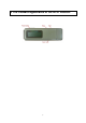
2 The Outward Appearance of the Wi-Fi Detector 3
3 How to charge the Wi-Fi Detector 1. Remove t he cap from the Wi-Fi Detector, slide the power switch to the “ON” position and carefully insert the USB connector into any available USB port on your computer. You will see the recharging screen. The battery strength indicator will be animated while the Wi-Fi detector is being recharged. The “Link/Act” icon will blink when the Wi-Fi detector is being used as a wireless USB adapter to surf the inter net. 2.
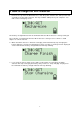
4 How to use the Wi-Fi Detector 1. Slide t he power switch to the “ON” position, and a welcome screen will greet the user. 2. After the welcome screen is displayed the Wi-Fi detector will automatically enter scanning mode to detect Wi-Fi signals. In scanning mode the display will display the total number of both non-encrypted and encrypted Wi-Fi signals detected. 3. Once scanning mode is complete, the detector will enter its standard display mode.
The Icons on the LCM display are displayed as follows: 1. Operating Channel: Indicates the current operating channel of the detected Wi-Fi signal. 2. Number of AP’s Detected: the left digit indicates which detected Wi-Fi signal is currently displayed and the right digit indicates the total amount of Wi-Fi signals detected. 3. Encryption indicator: “WEP” for WEP encryption, “WPA” for WPA encryption, and “WPA2” for WPA2 encryption, and “OPEN” indicates it is a non-encrypted signal. 4.
5 How to install the driver and utility Before you proceed with the installation, please notice following descriptions. Note1: Please do not install the USB adapter into your computer before installing the software program from the CD. Note2: The following installation was operated in Windows XP. (Procedures are similar for Windows 98SE/Me/2000/2003 Server.) Note3: If you have installed the Wireless PC Card driver & utility before, please uninstall the old version first.
B. If you want to install the software program in anot her location, click “Browse” and select an alter native destination. Then, click “ Next”. C. Click “Continue Anyway” to finish t he installation.
II. Install the USB adapter A. Plug the USB adapter into the USB port of your computer. B. The “Found New Hardware Wizard” is display ed, select “Install the software automatically (Recommended)” and click “ Next”. C. Click “Continue Anyway” and the system will start to install the USB adapter.
D. Click “Finis h” to complete the installation. III. Using the Configuration Utility To setup the USB adapter, double-click the icon in the system tray. For Windows XP, there is a “Windows Zero Configuration Tool” by default for you to setup wireless clients. If you want to use the Utility of the USB adapter, please follow one of the ways as below.
First Way A. Double-click the utility icon in the system tray. B. Click “Yes” to use the utility of the USB adapter. Second Way A. Double-click the icon. B. Click “Advance”. C. Uncheck “Use Windows to configure my wireless network settings”.
6 How to configure the utility The Configuration Utility is a powerful application t hat helps you configure the 802.11g Wireless LAN USB adapter and monitor the link status during t he communication process. The Configuration Utility appears as an icon on the system tray of Windows while the adapter is running. You can open it by double-click on the icon. Right click the icon, there are some items for you to operate the configuration utility.
Parameter Description Mode Station – Set the USB adapter a wireless client. Access Point – Tur ns the USB adapter to function as a wireless AP. Please refer to Section 6.5 for the AP settings. Network Adapter Display the product information of the USB adapter. Available Network Display all the SSID and Signal Strengt h of wireless stations nearby. To re-survey t he available wireless devices please click “Refresh”.
Parameter Description Signal Strengt h This bar shows the signal strength level. The higher percentage show n in the bar, the more radio signal been received by the adapter. This indicator helps to find the proper position of the wireless station for quality network operation. Link Quality This bar indicates the quality of the link. The higher the percentage, the better the quality. TX Frame It shows the number of data frames whic h are transmitted by the adapter successfully.
Parameter Tx Rate Description There are several options including Auto/1/2/5.5/11/6/9/12/18/24/36/48/54Mbps for you to select. When the “Auto” is selected, the device will choose t he most suitable transmission rate automatically. The higher data rate you designated in the network, the shorter distance is allowed between the adapter and the wireless stations. When the adapter works in 11b mode, the maximum data rate is 11Mbps so that there are only “Auto/1/2/5.5/11Mbps” options you can select.
Parameter Description Aut hentication Mode This setting has to be consistent with the wireless networks that the adapter intends to connect. Open System – No aut hentication is needed among the wireless network. Shared Key – Only wireless stations using a shared key (WEP Key identified) are allowed to connect each ot her. Auto – Auto switch the aut hentication algorit hm depending on the wireless networks that the adapter is connecting to.
6.3 WEP and WPA Encryption WEP is an data encryption algorit hm, which protects Wireless LAN data in the network against eavesdropping. WEP has been found t hat it has some security problems. The adapter supports WPA (Wi-Fi Protected Access) that combines IEEE 802.1x and TKIP (Temporal Key Integrity Protocol) technologies. Client users are required to aut horize before accessing to Aps or AP Routers, and the data transmitted in the network is encrypted/decrypted by a dynamically changed secret key.
Parameter Description Key1 ~ Key4 The keys are used to encrypt data transmitted in the wireless network. Fill the text box by following the rules below. 64-bit – Input 10-digit Hex values or 5-digit ASCII values as the encryption keys. For example: “0123456aef“ or “Guest“. 128-bit – Input 26-digit Hex values or 13-digit ASCII values as the encryption keys. For example: “01234567890123456789abcdef“ or “administrator“. 256-bit – Input 58-digit Hex values or 29-digit ASCII values as the encryption keys.
Parameter Description Connect Information Protocol User Name It is the setting for WPA mode. This adapter supports two kind of protocol for authentication including TLS and PEAP. TLS and PEAP requires a certificate which is provided by the Certificate Server. PEAP requires a set of user name and password in addition. To get the certificate and the personal user name and password, please contact with your administrator. TLS – Select a certificate from the “Certificate“ list.
Parameter Description WEP Key If the AP uses WEP data encryption function, please clcik “WEP KEY SETTI NG“ to setup the WEP key. WEP KEY SETTING Change/Apply 6.4 Setup the four sets of WEP key by clicking the button. Clcik “Change“ will enable you to setup the WPA setting. In the meantime, the button will change to “Apply“ for you to confirm your settings.
Parameter Description Power Consumption Setting Continuous Access Mode (CAM) – The adapter will always set in active mode. Maximum Power-Saving Mode – Enable t he adapter in the power saving mode w hen it is idle. Fast Power-Saving Mode – Enable the adapter in the power saving mode when it is idle, but some components of the adapter is still alive. In this mode, the power consumption is larger than “Max“ mode.
Parameter Description Mode Station – Set the USB adapter a wireless client. Access Point – Tur ns the USB adapter to function as a wireless AP. Network Adapter Display the product information of the USB Adapter. Connect Station List Display all the MAC Addresses of the wireless adapters which are connecting to the AP. Current Network Setting Display the connection setting of the current network. It includes Channel, SSID, WEP and TX Power Level.
6.5.2 AP General Connection Setting Click “More Setting”, users are allowed to setup the AP connection setting, Encryption Setting and ot her advanced functions. Parameter General Connection Setting Channel Basic Rate Description Select the number of the radio channel used by the AP. The wireless adapters which connects to the AP should set up the same channel. Select the basic data transmission speed supports by the AP.
Parameter Tx Rate SSID Description There are several options including Auto/1/2/5.5/11/6/9/12/18/24/36/48/54Mbps for you to select. When the “Auto” is selected, the device will choose t he most suitable transmission rate automatically. The higher data rate you designated in the network, the shorter distance is allowed between the adapter and the wireless stations. When the adapter works in 11b mode, the maximum data rate is 11Mbps so that there are only “Auto/1/2/5.5/11Mbps” options you can select.
Parameter Description Fragement The value defines the maximum size of packets, any packet size larger than the value will be fragmented. If you have decreased this value and experience high packet error rates, you can increase it again, but it will likely decrease overall network performance. Select a setting within a range of 256 to 2346 bytes. Minor change is recommended. RTS / CTS Minimum packet size required for an RTS/CTS (Request To Send/Clear to Send).
Parameter Description Filter Type Disable – Disable the MAC Address filter function. Accept – Only the wireless adapters with the MAC Address setup in the table can connect to the AP. Reject – The wireless adapters with the MAC Address setup in the table will be rejected to connect to the AP. MAC Address is a unique identification for hardware devices in the network. It is a 12-digit hexadecimal values. Filter MAC Address There are fifty sets of MAC Address can setup in the table.
7 Troubleshooting This chapter provides solutions to problems usually encountered during t he installation and operation of the adapter. 1. What is the IEEE 802.11g standard? 802.11g is the new IEEE standard for high-speed wireless LAN communications that provides for up to 54 Mbps data rate in the 2.4 GHz band. 802.11g is quickly becoming the next mainstream wireless LAN technology for the home, office and public networks. 802.
5. What is Infrastructure? An integrated wireless and wireless and wired LAN is called an Infrastructure configuration. Infrastruct ure is applicable to enterprise scale for wireless access to central database, or wireless application for mobile workers. 6. What is BSS ID? A specific Ad hoc LAN is called a Basic Service Set (BSS). Computers in a BSS must be configured with t he same BSS ID. 7.
12. What is DSSS?What is FHSS? And what are their differences? Frequency- hopping spread-spectrum (FHSS) uses a narrowband carrier that changes frequency in a pattern that is know n to both transmitter and receiver. Properly synchronized, the net effect is to maintain a single logical channel. To an unintended receiver, FHSS appears to be short-duration impulse noise. Direct-sequence spreadspectrum (DSSS) generates a redundant bit pattern for each bit to be transmitted.