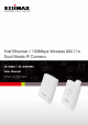
ErP Announcement Product: Internet Camera (IP Camera) Purpose: 24 hour surveillance and transfer of footage for safety and health reasons as intented use. Detailed description: - Health purposes: Users can pass through the Internet (from anywhere) to control the product (IP Camera). It's intended to watch and listen to people who need to be cared for at home and automatically sends e-mails and phone alerts to warn observers and ask for their attention.
Copyright by Edimax Technology Co, LTD. all rights reserved. No part of this publication may be reproduced, transmitted, transcribed, stored in a retrieval system, or translated into any language or computer language, in any form or by any means, electronic, mechanical, magnetic, optical, chemical, manual or otherwise, without the prior written permission of this company.
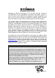
Table of Contents Chapter I: Familiar with your Internet IP Camera ............................................. 6 1.1 Package Contents .............................................................................. 6 1.2 Basic Introduction ............................................................................... 7 1.3 Product Highlights ............................................................................... 8 1.4 Familiar with Key Components ....................................................
2.10 Account ........................................................................................... 61 2.11 Log………………………………………………………………………..63 2.12 Language Menu .............................................................................. 64 Chapter III: Using Surveillance Software ....................................................... 65 3-1 Installing IP Camera Surveillance Software ...................................... 65 3-2 Using IP camera surveillance software ................................
Chapter I: Familiar with your Internet IP Camera 1.1 Package Contents Thank you for purchasing this IP camera! Before you start to use this IP camera, please check the package contents. If anything is missing, please contact the dealer of purchase and return the package to claim for missing contents.
1.2 Basic Introduction Congratulations on buying this Edimax IP Camera! You've chosen well. This IP camera is ideal for all kinds of video surveillance from home and office safety to child and pet monitoring purposes. This Edimax IP camera is tailor made to stream live video over your network, so you can view its footage from anywhere on your local computers.
1.3 Product Highlights No pre-loaded software required - all you need is a browser like Internet Explorer 6 (and above, with plugin installed). Supports VGA (640 x 480), QVGA (320 x 240), and QQVGA (160 x 120) video resolution, with auto-exposure control Supports two video compression formats (MJPEG and MPEG4). Supports all major web browser, including Microsoft Internet Explorer, Apple Safari and Firefox. Wired and wireless network (802.11b / 802.11g / 802.11n) support.
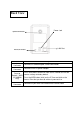
1.4 Familiar with Key Components Front View There are two LEDs indicating the camera's status and networking status.
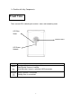
Back View Power Jack Tripod Connector LAN Port Reset to Default Name Tripod Connector Power Connector Description Connects to standard tripod / camera wall holder Connects to 5V DC power adapter Press and hold this button for more than 5 seconds to reset the Reset to camera settings to factory default. Default / *WPS (IC-3005Wn Press the WPS button (click) on the IP Cam and click on the only) Access Point that you want to wirelessly connect it to.
1.5 Camera Installation 1. Unpack your Edimax IP Camera from its packaging and ensure that all the items listed in Chapter 1 are there. 2. Connect the Edimax IP Camera to your network by attaching a network cable from your switch or router to the LAN port on the IP Camera. 3. Connect the power adapter to the IP Camera and plug the adapter into a power outlet. When the IP Camera is ready, the Blue LED will light up. Note: It is highly recommended to use only the power adapter shipped with the IP Camera.
1.6 Locate the IP Address of this IP Camera Default IP address of this IP camera is 192.168.2.3. If you wish to assign another IP address to this IP camera, you have to log onto the web configuration interface of the camera first. If the left three fields of the IP address of your computer is not 192.168.2, you‟ll have to change the IP address of your computer first: 1.
2. Double-click „Network Connections‟ icon. 3. Right-click „Local Area Connection‟, and click „Properties‟.
4. Select „Internet Protocol (TCP/IP)‟, then click „Properties‟.
5. In „IP address‟ field, please fill in any IP address begins with „192.168.2‟, and ends with a value greater than 2 and less than 254 (You can use the example in the picture „192.168.2.239‟). In Subnet mask field, please fill „255.255.255.0‟. Please keep all other fields empty, and click „OK‟. If you changed the IP address of this IP camera and you forget it, there‟re 2 ways you can recover it: a.
1.7 Log Onto Web Management Interface Make sure the IP camera is correctly powered (Power LED is on), and then launch Internet Explorer and type the IP address of the IP camera in address bar of Internet Explorer. You should be prompted to input the user name and password: Default user name is „admin‟ (in lower case) and password is „1234‟. Click „OK‟ to continue after user name and password has entered. If you‟re rejected, maybe the password has been modified previously.
After logged on, you should see the following messages at the top of Internet Explorer: If not, please go to section 1.8.1 „Install ActiveX‟. This IP camera requires a special ActiveX control (A.K.A. „Plugin‟) to work. Please click on the message, and select „Install ActiveX Control…‟: When you‟re prompted, click „Install‟ to continue.
You should be able to see the image from camera now: Note: If you see one of these messages (or both): OR Your computer may not have the display capability that this IP camera requires, or you don’t have Microsoft DirectX® installed. Please download Microsoft DirectX® from Microsoft’s website (http://www.microsoft.com), and try again. In some cases, your computer is able to display the image from IP camera correctly, but you’ll still see these messages. If this happens, just ignore them.
1.7.1 Install ActiveX Most of browsers support Microsoft ActiveX, but if ActiveX is not present on your computer, you need to install it before you can use this Internet camera.
Press „Next‟ to start installation; press „Next‟ button when you‟re prompted, until installation is complete: 20
Press „Finish‟ when you see this message. Now please go back to last section to install IP camera plugin.
Chapter II: Using Web Management Interface 2.1 Camera Settings The first menu after you logged onto web management interface is „Camera‟, and this is the only menu you can see the real-time image from camera. You can always back to this menu by clicking „Camera‟ on the top of web management interface.
The descriptions of every setting in this menu will be given below: Item Description Video Format Specifies video encoding format. You can choose MPEG4 or MJPEG (Motion-JPEG). MPEG4 mode also supports motion detection Snapshot Take a snapshot picture and save the picture to your computer‟s hard drive. Click on directory display and you‟ll be prompted to select a folder to save snapshot file. Record Start video recording and save recorded video clip to your computer‟s hard drive.
Fit to Window To exit digital zoom setting, press button. Click this button and captured image will fit to window size. *Note: If you‟re not using Microsoft Internet Explorer as web browser, some functionalities may not work properly.
2.1.1 About This function will provide you with the version number of current IP camera plugin, which is useful when you need online support. To see version information, right-click on the image.
2.2 LAN Settings All network-related settings can be found in this menu, and you have to specify TCP/IP parameters in this menu if you want to change IP address, use PPPoE, Dynamic DNS, and activate UPnP function. You can access this menu by clicking „LAN‟ on the top of web management interface. 2.2.1 IP Address You can define IP address and select the port number you wish to use here.
The descriptions of every setting in this menu will be given below: Item Description Network Type This camera can obtain the IP address from DHCP server automatically (if you have one), or set a fixed IP address. Select „DHCP‟ to obtain IP address automatically or „Static IP Address‟ to assign this IP camera with a fixed IP address. When „DHCP‟ is selected, IP address parameters below will be grayed out. IP Address Specify the IP address for this IP camera here.
2.2.2 RTSP RTSP (Real-Time Streaming Protocol) allows you to view live video captured by IP camera. You can set RTSP related settings here. The descriptions of every setting in this menu will be given below: Item Description Enable RTSP Select „Enable‟ to activate RTSP function of this IP camera, select „Disable‟ to disable it. RTSP Port Input the port number which RTSP will use. Default setting is 554. RTSP Path Input the path of RTSP stream. ** RTP Port Range Input the port range of RTP.
2.2.3 PPPoE Enable PPPoE Select „Enable‟ to activate PPPoE function of this IP camera, select „Disable‟ to disable it. User Name Input the PPPoE username assigned by your ISP here. Password Input the PPPoE password assigned by your ISP here. MTU Input the MTU (Maximum Transmission Unit) given by your ISP here. Ask your ISP if you don‟t know what value you should input here. Default value should work with most of ISPs and will give you a nice network performance.
2.2.4 Dynamic DNS If your ISP does not give you a fixed Internet IP address (i.e. the Internet address you‟re using when you access the Internet is not always the same – ask your ISP for detailed information), you can use this function to help you locate the IP address of this IP camera when you‟re away from home or office. Before you can use this function, you‟ll need to apply for an account at dyndns.org (http://www.dyndns.org). Detailed instructions of how to apply a new account can be found on dyndns.
2.2.5 UPnP When UPnP function is activated, all UPnP-compatible computers / network devices will be able to discover this IP camera automatically (only those in the same local network). This function is useful and you don‟t have to remember the IP address of this IP camera.
Click the message to open „My Network Places‟, and you‟ll see the IP camera: You can double-click the icon to launch Internet Explorer and log onto IP camera‟s web management interface directly.
2.2.6 LoginFree You can specify a filename here, and everyone who knows this filename can gain access to the picture captured by the IP camera with this name with .jpg file extension. For example, if the filename you specified here is „loginfree‟ and your IP camera‟s IP address is „192.168.2.3‟, then everyone on the network can access to the picture taken by the IP camera at „http://192.168.2.3/loginfree.jpg‟.
2.3 WLAN Parameters If you wish to use wireless network instead of wired network connection, you have to set wireless LAN parameters here. You can access this menu by clicking „LAN‟ on the top of web management interface.
The descriptions of every setting in this menu will be given below: Item Description Self PinCode A random 8-digit code will be displayed here. If the wireless AP you wish to connect supports PINCODE, please input this code to the AP you wish to connect. This code changes every time you enter this page. Configure via Push Button If the wireless AP you wish to connect supports push button WPS configuration, click „Start PBC‟ and press the WPS button on the wireless AP to start pairing.
to connect does not appear, you may have to click „Refresh‟ button for several times until it appears. The descriptions of all fields is listed below: Connect: You can select the wireless access point you wish to connect here.** SSID: the SSID of all found wireless access points will be shown here. Some wireless access point may hide their SSID, in this case, you have to identify them by their MAC address.
selected choose to hide it‟s SSID), you have to know it‟s SSID and input it here, or you will not be able to connect it. Channel Select the radio channel you wish to use here. When network type is „Infrastructure‟, the radio channel is auto-selected according to the channel that wireless access point uses. You can only select the channel number when network type is „Adhoc‟. Basic Rate Select the maximum wireless data transfer rate here, from 1Mbps to 54Mbps. Maximum transfer rate for 802.
options available here will vary depends on the authentication type you selected above. If an authentication type does not support need encryption, this field will be grayed out. WPA Pre-Shared Key Input the WPA pre-shared key here. This field is only available when authentication type is WPA-PSK or WPA2-PSK, and will be grayed out when other authentication type is selected. WEP Key Length Please select the key length when you use WEP encryption. Available options are 64-bit and 128-bit.
only have one WEP key. WEP Key 2 Input the 2nd set of WEP key here. WEP Key 3 Input the 3rd set of WEP key here. WEP Key 4 Input the 4th set of WEP key here. Click „Apply‟ to save settings and make the new settings take effect.
2.4 Video You can specify the video and audio parameters of this IP camera here.
2.4.1 Dual Mode This IP camera supports two video encoding formats: MPEG4 and MJPEG. You can select the encoding format from one of them. The descriptions of every setting in this menu will be given below: Item Description Default Video Specify default video encoding format of this IP camera Format here. Available options are MPEG4 and MJPEG. Click „Apply‟ to save settings and make the new settings take effect.
2.4.2 MPEG4 If you selected „MPEG4‟ as the video encoding format of this IP camera, you can specify the parameters of MPEG4 video encoder here. The descriptions of every setting in this menu will be given below: Item Description Video Resolution Specify video resolution of MPEG4 video encoder. Available options are VGA and QVGA resolution. VGA resolution provides more details than QVGA, but requires more network bandwidth. Video Quality Specify video quality.
2.4.3 MJPEG If you selected „MJPEG‟ as the video encoding format of this IP camera, you can specify the parameters of MPEG4 video encoder here. The descriptions of every setting in this menu will be given below: Item Description Video Resolution Specify video resolution of MJPEG video encoder. Available options are VGA (640x480), QVGA (320x240), and QQVGA (160x120) resolution. VGA resolution provides more details than QVGA and QQVGA, but requires more network bandwidth.
2.5 Email & FTP This IP camera is capable to send an Email or perform FTP upload with captured image, when a motion is detected. This is very convenient since IP camera will guard the environment automatically for you, and you don‟t have to look at the monitor all the time. You can access this menu by clicking „E-Mail & FTP‟ on the top of web management interface. The instructions of Email and FTP settings will be given below.
2.5.1 Email Settings These settings are used to send the captured picture via Email: The descriptions of every setting in this menu will be given below: Item Description Recipient E-Mail Address Input the email recipient‟s Email address here. If you have more than one Email recipient, please add a ; (semicolon) mark between every Email address. All characters shouldn‟t exceed 127 characters.
encryption. If in doubt, ask your ISP or mail server‟s administrator. SMTP Authentication Some SMTP server requires mail senders to be authenticated before they can send Email. If your SMTP server requires you to do so, please select „Enable‟, or select „Disable‟ to disable it. If you don‟t know, please refer to the SMTP server you‟re using in your Email software (like Outlook, Outlook Express etc.), or ask your network administrator or ISP.
2.5.2 FTP Settings These settings are used to send the captured picture by FTP: The descriptions of every setting in this menu will be given below: Item Description FTP Server Input the IP address or host name of the FTP server you wish to use here. FTP Port Input the port number of the FTP server you wish to use here. User Name Input the user name of the FTP server you wish to use here. Password Input the password of the FTP server you wish to use here.
found that non-passive mode is not working, you can try to use passive mode. Click „Apply‟ to save settings and make the new settings take effect. After that, you can click „Upload a test file‟ to send a file to the FTP server you set here, so you can make sure the setting you specified here is correct and working.
2.6 Motion Detection 2.6.1 Basic Settings Motion detection function makes this IP camera become your non-stop guard. You don‟t have to waste all the time monitoring the images from the camera, and camera will detect all motions for you. Once motion is detected, a captured image will be sent to you by Email or via FTP. You can access this menu by clicking „Motion Detection‟ on the top of web management interface.
interval is too short, you may receive too much unnecessary images, and consumes too much disk storage spaces on Email and / or FTP server. Pre Recording Time This option allows the IP cam to capture additional image frames prior to the event. The duration of pre recording is based on the settings of Resolution and estimated by the IP cam automatically. Recording Time Select the duration you wish this camera to record image when a motion is detected from dropdown menu.
2.6.2 Setup Motion Detection Regions If you only want to be notified when motion is detected in certain area of captured image, you can use this function and motions outside of motion detection region will be ignored, so you won‟t receive too much „useless‟ notifications. This IP camera supports up to 3 motion detection regions.
The descriptions of every setting in motion detection menu will be given below: Item Description Region1 / Region2 / Region3 Check the box to enable / disable a certain motion detection area. Sensitivity Control the detection sensitivity of motion detection of respective motion detection region. When sensitivity is higher, small changes in image will cause IP camera to send a Email / FTP notification; if you received too much unwanted notification, try to set sensitivity to a lower value.
2.7 Schedule You can control FTP / Email image transfer by schedule. Unlike motion detection, the only key to trigger file transfer is time. You can access this menu by clicking „Motion Detection‟ on the top of web management interface. The descriptions of every setting in this menu will be given below: Item Description Enable FTP Schedule Enable or disable FTP scheduling. Time Interval Select the time interval between 2 FTP file transfers.
Upload files with filename composed of date / time: When a file is uploaded, it will be named as the date and time when the file is uploaded. Over file with the same filename: When a new file is uploaded, it will replace the old one with the same file you specified here. Enable E-Mail Schedule. Enable or disable E-mail scheduling. Time Interval Specify the time interval between 2 emails. Click „Apply‟ to save settings and make the new settings take effect.
2.8 System The system menu allows you to set some system-specific parameters, like password and time setting. You can also upgrade the firmware of this IP camera, to make new functions available on this IP camera. You may also clear all settings or reboot the IP camera here. You can access this menu by clicking „System‟ on the top of web management interface.
2.8.1 Camera Information Camera information allows you to set the name and administrator‟s password of this camera. The descriptions of every setting in this menu will be given below: Item Description Camera Name Please specify the name of this IP Camera here. This can be used to identify your camera on the network when you have more than one IP camera in the same network. Default name begins with „IC-„ plus the last 6 characters of the MAC address of this IP camera.
2.8.2 Date / Time Setting This setting allows you to change the date and time of the real time clock in this IP camera. You can set the time manually, or use network time protocol (NTP) to set the time automatically. The descriptions of every setting in this menu will be given below: Item Description Set Date/Time manually Please input the date and time you wish to set here. Date / time format is YYYY / MM / DD HH:MM:SS Time is in 24-hour format.
2.8.3 Utilities This menu allows you to upgrade firmware, clear all settings, reboot the IP camera, and switch LED lights on/off. The descriptions of every setting in this menu will be given below: Item Description Upgrade Firmware If you downloaded latest firmware file from our website, you can click „Browse‟ button to pick the firmware file you wish to use. Then click „Upgrade‟ button to start firmware upgrade procedure.
you don‟t want other people know the camera is transferring data. You can click this button again to switch LED lights on again.
2.9 Status This menu provides all information about this IP camera, like firmware version, system uptime, date / time, and network information. You can access this menu by clicking „Status‟ on the top of web management interface.
2.10 Account If you wish to allow other people to view the image captured by this camera, but don‟t want to allow them to modify system settings, you can give them user-level user name and password, so they can only view the image and can not change any system setting. When they want to click menus other than „Camera‟, they will see the following message informing that they don‟t have permission to do that: This IP camera supports up to 16 user accounts.
The descriptions of every setting in this menu will be given below: Item Description Login Specify the user name here. Please use alphanumerical characters (0 to 9, A to Z, and a to z). Not using symbols and space. Password Specify the password for this user here. Confirm Password Specify the password for this user here again. Authority Select „Operator‟ and this user will be able to change the settings of IP camera; select „Guest‟ and this user can only view the image.
2.11 Log All activities of this IP camera will be logged, and you and enter „Log‟ menu to view these logs. You can access this menu by clicking „Log‟ on the top of web management interface. Click „Refresh‟ to get latest update.
2.11 Language Menu This IP camera‟s user interface supports multiple languages. To change language, click „Language‟ dropdown menu: Select a language you wish to use from dropdown menu to change displaying language.
Chapter III: Using Surveillance Software 3-1 Installing IP Camera Surveillance Software The IP camera surveillance software provides various functions like video recording, after this software is installed, you can use your IP camera to safeguard your property. Please follow the following instructions to install the surveillance software. 1. Click “16 channel viewer” in supplied CD-ROM, when the following window appears, click „Next‟. 2.
3. If you need installation program to create a desktop icon or a quick launch icon for you, click all items you need here, than click „Next‟ to continue.
4. Here lists all options you chose in previous steps, if everything‟s correct, click „Install‟ to start installing procedure, or click „Back‟ to go back to previous step to modify installing settings. 5. The installing procedure will take some time, please be patient.
6. When you see this window, it means the software installing procedure is complete. Please click „Finish‟ to finish the procedure (IP camera surveillance software will start after you click „Finish‟ button, if you want to start it later, uncheck „Launch IPCam Surveillance Software‟ box).
3-2 Using IP camera surveillance software You can click „IPCam Surveillance Software‟ icon from desktop, quick launch bar, or start menu to start the IP camera surveillance software. Before you start: IP camera surveillance software will only work when your monitor’s resolution is ‘1024 x 768’. Please change the resolution before you use IP camera surveillance software, or it won’t start.
You can put the mouse cursor on a certain component and see its button name, and here‟re detailed descriptions of all buttons: Item Description Video displaying area The image of all connected cameras will be displayed here. Language Select a language from this dropdown menu to change display language. Display layout Change camera image display layout (Click a layout icon to change camera display layout). There are 8 kinds of available display layouts.
Playback Playback a recorded video file. Snapshot Take a snapshot of current camera. Message display Displays all system messages like camera is disconnected etc. Close window (stop surveillance) Terminates IP camera surveillance software. Minimize window Minimizes IP camera surveillance software window. Video displaying area Displays the image of all cameras by the display layout you selected.
3-3 Configure IP camera surveillance software 3-3-1 Configure cameras Before you use this IP camera surveillance software, you must configure the camera(s) you wish to connect.
3-3-1-1 „Camera‟ tab In this tab you can configure all cameras you wish to connect. Up to 16 cameras can be connected simultaneously: Here are the descriptions of all setting items: Item Description Channel Select the channel number you wish to set. Camera Search All cameras found on your local network will be displayed in „Camera Search‟ box.
IP* Input the IP address of camera. Username* Input the user name of camera. Web Port* Input the web port of the camera. By default it‟s „80‟. Password Input the password of camera. Default value is „1234‟. You should change the password if you changed the password of selected camera. Video Format** Select the video encoding format of this camera (MJPEG or MPEG4). Reset Clear all fields in „Camera Configuration‟ section. OK Save settings in this tab. Cancel Discard all settings in this tab.
3-3-1-2 Schedule Recording In this tab, you can setup scheduled video recording, so you can record the video captured by all cameras you have by a pre-defined schedule. Here are the descriptions of all setting items: Item Description Channel Select the channel number you wish to set. One Time Schedules You can specify the one-time schedule for selected camera; this schedule will be executed once only.
Please specify the time duration of this one-time schedule (the date and time of „From‟ and „To‟), then click „OK‟ to save settings. Please note you must set a schedule that will be happened in the future, you can not set a schedule in the past. Edit You can modify a scheduled recording item. Select a schedule in „One Time Schedules‟ list, and click „Edit‟ button to edit the start and end time of this schedule. Delete Delete a selected schedule item.
Please check all weekdays that applies, and set the start time in „From‟ field. You can set the duration of video recording in „Period‟ field (format is HH:MM:SS), and the end time will be calculated automatically and displayed in „To‟ field. You can also click „All Time Record‟ button to define a recording schedule that will be executed every weekday, from 12:00:00AM to 11:59:59PM. Click „OK‟ to save changes. Edit You can modify a scheduled recording item.
3-3-1-3 Audio For cameras that support audio, you can use this tab to decide if you wish to hear the audio captured by selected camera. Here are the descriptions of all setting items: Item Description Channel Select the channel number you wish to set. Mute Audio Check this box and the IP camera surveillance software will not play the audio captured by this camera. Record Video Only Check this box and the IP camera surveillance software will not record the audio captured by this camera.
3-3-1-4 Motion Record With this function activated, only motions captured by the camera will be recorded, so you don‟t have to waste hard disk storage space on images you don‟t need to pay attention to. WARNING: For applications that security is highly concerned, it’s not recommended to use this function since some tiny changes you may need to know may not be able to trigger the camera and the camera will not start recording.
motion is has been detected by the camera. triggered OK Save settings in this tab. Cancel Discard all settings in this tab.
3-3-2 General Settings You can set system-wide settings of this IP camera surveillance software in this menu. 3-3-2-1 „General‟ tab All general settings like file storage directory and recording spaces can be set here. Here are the descriptions of all setting items: Item Description Data Directory Set the directory (folder) you wish to store the recorded video and captured image. You can click „Browse‟ button to pick a directory in your hard disk. Free Recording Space Displays remaining storage space.
Scan Time Define the time period to pause between every camera switch when you activate „Scan‟ function. Cycle Recording You can decide the behavior when hard disk space is full: Disable: Do not overwrite recorded video files. Enable: Overwrite recorded video files. OK Save settings in this tab. Cancel Discard all settings in this tab.
3-3-2-2 „E-Mail Setting‟ tab If you want to use motion detection function and wish to get an email that contains the image captured by the camera, please setup your email related parameters here first. Here are the descriptions of all setting items: Item Description E-Mail Subject Specify the subject of sending email. Recipient E-Mail Address Here lists all email addresses you set. New Click this button and you‟ll be prompted to input the email address. Click „OK‟ to save changes.
Edit Select an email address from „Recipient E-Mail Address‟ box, and click „Edit‟ to edit the email address. Delete Delete selected email address. Sender E-Mail Specify the email address of email sender. Address SMTP Server Specify the IP address or host name of the SMTP server you wish to use.
3-3-2-3 Security If you don‟t want other people to access this IP camera surveillance software, you can set a password to protect it.
Here are the descriptions of all setting items: Item Description Enable Requires password authentication when this software starts. Disable Password authentication is not required when this software starts. Password Input the password you wish to use here. Confirm Password Input the password you wish to use here again. 3-3-2-4 About This tab shows the version number of the IP camera surveillance software you‟re using.
3-4 Change Display Layout This IP camera surveillance software provides 8 kinds of display layout: Every layout displays different number of camera and camera arrangement, you can click the icon that presents a specific kind of layout, and the video displaying area will change accordingly. Layout style 1: 1 Camera only Displays the video of 1 camera only. Layout style 2: 4 Cameras Displays the video of up to 4 cameras.
Layout style 3: 6 Displays the video of up to 6 cameras. Cameras Layout style 4: 8 Cameras Displays the video of up to 8 cameras. Layout style 5: 9 Cameras Displays the video of up to 9 cameras. Layout style 6: 10 Cameras Displays the video of up to 10 cameras.
Layout style 7: 13 Displays the video of up to 13 cameras. Cameras Layout style 8: 16 Displays the video of up to 16 cameras.
3-5 Full-screen mode If you want to use all available spaces on your monitor to display surveillance image, you can click „Full Screen‟ button to switch display mode to full-screen mode. To exit full-screen mode, press „ESC‟ key.
3-6 Scan If you have more than one camera configured, and you wish to switch the displaying image between cameras, you can click „Scan‟ button to switch between all configured cameras. NOTE: If a camera is configured but disconnected, it will still be displayed in a scan sequence (you’ll see nothing and you’ll see ‘Disconnected’ text displayed at the upper-left corner of display image).
3-7 Zoom-in / Zoom-out For cameras that support zoom-in / zoom-out function, you can use this function to see more objects that fall in the scope of camera‟s view, or enlarge the image size of a certain object to see its detail.
3-8 PTZ For cameras that support pan - tilt function ( but this model doesn‟t support PTZ function), you can change the position that camera points to, to see different places that fall in the scope of camera‟s view. Please select a camera in video displaying area by clicking on its image, and then click the directions you wish the camera to move to (total 8 directions available). Click „Home‟ button ( ) to return to camera‟s home (default) position.
3-9 Snapshot You can take a snapshot of selected camera and save it to „Snapshot‟ sub-folder of pre-defined data directory. Click snapshot button once to take a snapshot; you can take as much snapshot as you want before hard disk is full.
3-10 Recording You can start video recording of selected camera manually by clicking „Start Recording‟ button: When recording starts, you‟ll see a message displayed in message displaying box like „1/1 10:00:00, Camera 2 Start Manual‟, which means camera 1 starts recording manually on 1/1 at 10:00:00. To stop recording, click „Start Recording‟ button again, and you‟ll see a message displayed in message displaying box like „1/1 10:00:00, Camera 2 Stop Manual‟.
3-11 Video Playback You can playback all recorded video by clicking this button. A new window will appear: You have to search the video file before you can play it. There are two kinds of video search: Time Search (search all videos file that falls in a specific period of time) and Motion Search (search all videos recorded by motion detection function and falls in a specific period of time).
Chapter V: How to View IP Camera over the Internet with iPhone IC-3005 series features iPhone support for iPhone users to monitor their home using Edimax IP-Cameras. Please check following instruction for installation. The following instruction applies to all Edimax routers Step1: Ensure My-PC is Internet-ready via Router Step 2: Check with your ISP (Internet Service Provider) whether a Public and fixed IP address is assigned to you.
DNS account in the http://www.dyndns.org ” In this guide, we assume you have already got http://my-name.dyndns.org. (yours may vary) and go to Step 3.
Configure the Broadband Router based on the following: 99
Step 4: Configuration for iPhone. (1) Make sure Internet connection is ok with iPhone and click “Safari” (2) Enter the IP address of your router‟s “fixed and public IP address” (check the Step 2 for details) Note: “/ipcam.asp” is needed If no fixed and public IP address is given by your ISP, you may enter a link like http://my-name.dyndns.org/ipcam.asp (Again, this link is hypothetic) You could have your own name like http://john.dyndns.org, mary.dyndns.org etc.
(3) Enter user name & password for the Edimax IP camera. By default, user name is admin and password is 1234 (4) Let‟s add the 1st IP camera. Click first window and Setting.
(5) Click “Add” when finishing the following configuration: (6) Click “Add” when finishing the following configuration for the 2nd IP camera 102
(7) Configuration is complete. You could see the live video of the 2nd IP camera.
Chapter V: Appendix 5.1 Troubleshooting If the IP camera is not working properly, before you contact the dealer of purchase for help, please check the troubleshooting list here, this may help you to solve the problem by yourself and therefore saves your valuable time. Scenario Possible Solution I can not connect to IP camera a. Please confirm the IP address setting of the computer you‟re using. If they‟re not in the same subnet, they will not be able to communicate with each other. b.
c. If you‟re connecting this camera from Internet, it could be caused by a slow Internet connection, and it‟s not a problem caused by camera. However, when the network connection is slow, you should use lower frame rate / resolution. d. Adjust the antenna if you‟re using wireless connection. The antenna should be perpendicular to the ground to get best reception, and the distance between IP camera and computer / wireless access point should not be too far. e.
to send image by Email or FTP, but nothing is received not blocked by any anti-spam mechanism. b. Please make sure you have enough permission for FTP uploading (You can try this by clicking „Upload a test file‟ button). c. Make sure the user name and / or password of SMTP server is correct, if your SMTP server requires authentication (You can try this by click „Send a test Email‟ button). d.
5.2 Obtain a free Dyndns account If your ISP is issuing dynamic (non-static) IP address to you and you can‟t connect to your IP camera when you‟re away from it, you can follow the following steps to obtain a free Dyndns account, which will provide you free IP address to host name mapping service: 1. Launch your web browser and navigate to http://www.dyndns.org 2. Click „Sign In‟ button (located at upper-right corner of dyndns.
3. Click „Create an Account‟ in pop-up menu. 4. Fill all fields appear in this menu, and click „Create Account‟ button to create a new account. You‟ll be prompted if the account you selected is not available.
5. When you see this image, you‟ll receive an e-mail confirmation at the e-mail box you registered with dyndns.org. 6. Check your e-mail box and you should be able to get confirmation e-mail. Click the link to connect to dyndns.org website and complete registration procedure. If you didn‟t get the mail, please re-check the e-mail address, or click „resending it‟ link in last step. Also, if nothing happen after you click the link, please copy the link text and paste it in web browser‟s address bar.
7. When you see „Account Confirmed‟ webpage, indicates your dyndns.org account has been confirmed and activated. Now you can click „Create a dynamic DNS host within our Free domains‟ link to continue. 8. Click „Create Hostname‟ button.
9. In this page: Input the hostname of your choice in „Hostname‟ field, Select a domain name in dropdown menu, Select „Host with IP address‟ for „Service Type‟, Input current IP address in „IP Address‟ field (or click the link below to use detected IP address to fill this field‟. 10. Click „Add to cart‟ continue.
11. Click „Next‟ to continue. 12. Click „Activate Services‟ to continue. 13. When you see this message, indicates your free dyndns.org hostname mapping service has been activated. You can go to chapter 2-2-3 to use your dyndns.
5.3 Use this IPCAM with a router or firewall If this IPCAM is not directly connected to Internet (behind router or firewall), you‟ll need to setup your router / firewall so you can access this IPCAM from other computers on Internet. The following instruction describes how to configure your router or firewall device so your IPCAM can work with them. These instructions are based on a commonly-available residential router and these setup techniques should be easy to apply on any other similar devices as well.
3. Enable Dynamic DNS function, select „DynDNS‟ as service provider, and fill the information you obtained from Dyndns.org into Domain name, Account, and Password field (these field‟s name may different on your router). 5.3.2 Open Ports Required by IP CAM To access IP CAM located behind router or firewall, you must open ports on router or firewall so you can access IP CAM from Internet. 1.
IP CAM web configuration and view live image: 80 AV Control Port: 4321 RTSP: 554 and 50000 to 60000 Please note that if you changed the port number of web configuration / view or RTSP, you have to change the port forwarding setting for your router accordingly. 3. If IP CAM is the only one service you wish to access from Internet, you can also use „DMZ‟ function to access IP CAM: Simply fill the IP address of IP CAM and you can access IP CAM from the IP address of your router directly.