-
i-WATCHER Pan / Tilt Internet IP Camera User Manual Version 1.0 March.
-
Table of Contents 1. System Features 1-1.Package Contents 1-2.System Requirements 1-3.Hardware Description and Features 1-4.i-WATCHER Hardware Specification 2. Installation 2-1. i-WATCHER Hardware Setup 2-2. i-WATCHER Hardware Setup (Wireless LAN Setup) 2-3. Connecting to an Access Point (AP) 3. Accessing the i-WATCHER 3-1.Change the i-WATCHER IP Status 3-2.On the LAN with DHCP Server 3-3.On the LAN without DHCP Server 3-4.On the LAN use with the ADSL Router 3-5.
-
8-3-3. Motion detected mail 8-3-4. Motion detected message on the main window. 8-3-5. FTP uploads when motion detected. 8-4.Alert IN Setup 8-4-1.Alert IN Setup 8-4-2.Alert IN with motion detected mail function(mail setting) 8-4-3.Motion detected mail (Alert IN Enabled) 8-4-4.Motion detected messenger on main window(Alert IN Enabled) 8-4-5.FTP uploads when motion detected(alert IN Enabled) 8-5. Network Setup 8-5-1. Manual Setup 8-5-2. Connect to ADSL by PPPOE mode 8-6. Audio Setup 8-6-1. Audio Configure 9.
-
14. Network Utilities 14-1. Determining your IP Address and Network Settings 14-2. Using PING 14-3. IPEdit search tool 15. POE(Power over Ethernet) Function 16. Pan and Tilt Control 16-1.Control the camera in the main window 16-2.Position Points Pre setting 16-3.Image Rotate Setting 16-4.Camera Moving Step Size 17. html code for you Website or Blog 18.
-
OVERVIEW 1. System Features Remote Surveillance Becomes Handy i-Watcher IP-Cam network camera let you monitor your surveillance system remotely anywhere around the world. It's a mini PC that comes with a camera where you can say "NO" to invest another PC specifically for surveillance purpose, uncomplicated installation and training, and yet with unlimited expansion, all you need is just a power and network cable and it's all DIY.
-
Audio and Video Recording Function With the highly sensitive built-in microphone, i-Watcher IP-Cam provide you with the recording of audio and video function, unlike those in the market where you can only record video without the audio. IP-Cam DVR Software IP-Cam DVR is mainly Windows based DVR software for building multi- channel video and audio surveillance DVR. IP-Cam DVR software ranges from entry level I-Watcher IP-cam to the flagship, i-WATCHER IP-Cam full series products support.
-
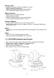
1-3. Hardware Description and Features z z z z z z z z z z z z z z z z z z z z z z Stand-alone network camera for flexible installation. Simple installation and multiple mounting methods. Embedded Web Server Supported. No computer is needed at the monitored site. Access live video via web browser at anytime and any place for remote surveillance and management. 2 default HTTP ports supported, they can be changed to fit different network environments.
-
Wireless LAN z z z z Support USB Wireless Dongle for IEEE802.11 b and g Zydas Chipset WiFi USB Dongle E-Mail the Detected Images to preset e-Mail address. FTP the Detected Images to preset FTP server. Motion Detection z z z z Software Real-Time Motion Detection. Selected Region Provided. E-Mail the Detected Images to preset e-Mail address. FTP the Detected Images to preset FTP server. Browser Supports z z IE only (ActiveX Control) saves the current image local PC.
-
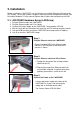
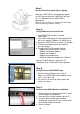
2. Installation Before installing the i-WATCHER, you should have an available Ethernet LAN connection (RJ-45 port). To view the camera’s image or make any manual configuration changes, you will need a Windows PC with Internet Explorer 6.0 or higher and connection to the LAN. 2-1. i-WATCHER Hardware Setup (LAN Setup) 1. 2. 3. 4. 5. 6.
-
Step 4. Ensure the Camera power light is lighting When the i-WATCHER is connected with power, the LED light on top of the i-WATCHER will light up. This indicates that the i-WATCHER is powered on. Wait 45 sec to 60 sec, camera will auto pan tilt and moving camera center Step 5. Using IPEdit.exe to test the IP-Cam 1. Use IPEDIT.EXE to find the installed i-WATCHER. 2. The i-WATCHER without IP allocated by DHCP will have a default IP Address of 169.254.xx.xx. 3. Select this i-WATCHER on Camera List Window. 4.
-
2-2. i-WATCHER Hardware Setup (Wireless LAN Setup) The i-WATCHER provides a USB port for extra device. Check the diagram for extra function i-WATCHER IP-Cam support wireless LAN USB Dongle, the USB port in camera back panel. The camera support dual mode, LAN and WLAN, when you want to use wireless LAN with i-WATCHER, please follow setup step and notes. 1. 2. 3. 4.
-
9. Use IE Browser to watch IP-cam image (wireless mode) 10. If you can find camera in IP-EDIT list and see camera video from IE, than mean is your camera wireless setup complete, when camera in wireless mode, IP-Edit software can’t change any setting, you must use IE into setup page to change camera setting. 11. Configuration page -> Network -> Disable LAN 12. Remove LAN Cable from camera RJ-45 connector and select “Reboot Immediately” button for reboot again (wait 60 sec) 13.
-
3. Accessing the i-WATCHER 3-1. Change the i-WATCHER IP Status Using the IPEdit.exe, you could select the different network options. The PC network options will display the Gateway and Net mask network settings, Which you can edit with IPEdit.exe . Alternatively, you may contact your network system administrator to provide you with the details of your network Gateway and Net mask settings. Enter the Camera’s IP number. If you allow outsiders to see the i-WATCHER, please enter another IP address.
-
3-2. On the LAN with DHCP Server 1. Use IPEDIT.EXE to find the installed i-WATCHER. 2. Select this i-WATCHER in the Camera Lists Window. 3. The default configurations will be shown in the right window. 4. Update the Camera’s IP status. 3-3. On the LAN without DHCP Server 1. Use IPEDIT.exe to find the installed i-WATCHER. 2. The i-WATCHER without IP allocated by DHCP will have a default IP Address of 169.254.xx.xx. 3. Select this i-WATCHER in the Camera Lists Window. 4.
-
A. Setup the mapping of HTTP Port (80) to 192.168.0.49. B. Restart the ADSL router. Then the i-WATCHER can be accessed from WAN, by the ADSL WAN IP Address. 3-5. Access the i-WATCHER by ordinary user login. If the user accesses the i-WATCHER by an ordinary user account, the i-WATCHER would not allow the user to access the privileged functions. From the following screen, the Camera Control, Resolution, Quality, and Configuration are disabled. 4.
-
3. Select “Yes“ then press “Set” button , check box will enable the user check when the users want to access the i-WATCHER. The login window will prompt for the User name and Password. 6. Camera Control On the IE Browser, right mouse click on the video to activate a pop-up menu. You can then change the camera settings accordingly. 6-1. Quality Setting The i-WATCHER provides 3 image quality settings. The user can select the setting from the Quality list box.
-
To control the camera, use the “+” to increase, “-“ to decrease it, or “STD” to return to default value. 6-5.Operation Mode Continuous Mode: The i-WATCHER will always try to capture the image as fast as possible. This is the default setting. Periodic Mode: MS (mill-second) or s (second) can be set. The value set must be greater than 0. Setting the periodic mode to 5 seconds will update the image every 5 seconds. The time interval can be checked by the time displayed on the image. 7.
-
8. Configuration Only the administrator can select the “Configuration”; the ordinary user account does not have this privilege to access this function. The screen is the main menu for configuration setting, when the administrator selects the “Configuration” in the main window. i-WATCHER provides 6 types of configurations: System Setup User Setup To add/delete user, change password; Enable/Disable user check. Add / Delete User Account. Change Password.
-
8-1. System Setup 8-1-1. Camera Name The camera name can be set on the “Camera Name” field, and select “change “ to summit it . 8-1-2. Camera’s time Select “ NTP ” button X Key in the Sever IP address like: http://www.org.ntp.org Press ”adjust” to activate Y After i-WATCHER get the time from NTP sever, it will update the Camera’s time field.
-
8-2. User Setup 8-2-1. User Management User authorization required: Checking the Enable use check function will enable the user check when the users want to Access the i-WATCHER. The Login window will prompt for the User name and Password. If the check box is not checked, then the user check will not be enabled. All users can access the i-WATCHER directly, with the administrator’s permission. A Login window is not required.
-
8-3-2. Motion detected mail function (Mail Setting) When motion detection is enabled, the user can setup the mail function to send the motion-detected images to the preset mail address. The procedures are as follow: X Motion Detect set to “Enable” state. Y Setup the “SMTP Mail Server” and E-Mail address. (Password use or not) Z Enter the sender’s email address in “Sender” field and the recipient’s email address in the “Receiver” field. [ The user can change the “Subject” field.
-
8-3-5. FTP uploads when motion detected. The motion-detected images can also be uploaded to FTP server. The procedures are as follow: X Enter the IP address or domain name of the “FTP Server”. Y Enter the “Username” and “Password” of the FTP server. Z Certain FTP servers need an “Account” field. Leave it blank if it is not needed. [ Enter the “Remote folder” upload path information for saving the images. \ Confirm by selecting the [Save Settings] option to save the settings. 8-3-6.
-
8-4-2. Alert IN with Motion detected mail function (Mail Setting) When motion detection and Alert IN is enabled, the user can setup the mail function to send the motion-detected images to the preset mail address. The procedures are as follow: X Motion Detect set to “Enable” state. Y Setup the “SMTP Mail Server” and E-Mail address. (Password use or not) Z Enter the sender’s email address in “Sender” field and the recipient’s email address in the “Receiver” field. [ The user can change the “Subject” field.
-
8-4-7. FTP uploads when motion detected (Alert IN Enabled) The motion-detected images can also be uploaded to FTP server. The procedures are as follow: X Enter the IP address or domain name of the “FTP Server”. Y Enter the “Username” and “Password” of the FTP server. Z Certain FTP servers need an “Account” field. Leave it blank if it is not needed. [ Enter the “Remote folder” upload path information for saving the images. \ Confirm by selecting the [Save Settings] option to save the settings. 8-5.
-
] Enter the “User” and “Password” fields with the account and password provided by the ISP. If the “Mail after dialed” check box is checked, the mail will be automatically sent when connected automatically to the ISP. ^ If the mail server needs authentication, the “Password” check box needs to be checked and password information, entered. _ Enter the sender’s email address in the “Sender email” field and recipient’s email address in the “Receiver email” field. ` The “Subject” field can be modified.
-
9. Snapshots 9-1.Snapshots Click “Snapshot” button, the Panel will appear the image, save as file.
-
10. Image Recording 10-1. Save as JPEG 1. Select “Image Recording…” 2. The “Image Recording” pop-up window displays. Check the “Save as JPEG” check box option. 3. Enter the “Download Number” to save the desired number of images, or “Download No Limit” to save the images continuously, until the “Stop Image Recording” is selected. 4. Click on the “Save As” button and a pop-up window displays to select the save path and file name prefix. Select “Save” to continue. 5.
-
[ Selecting the “No Limit” radio button will save the video file until the “Stop Image Recording” is selected. \ For each AVI file, the maximum number of images that can be saved in each file Are specified in “Max Jpeg Num” Once the images that can be saved on each AVI file are reached by this number, a new AVI file will be created to save the remaining images, until the “Stop Image Recording” is selected.
-
12. Hardware Reset Function Use Pin to push Reset button hole 10 sec, the Camera will reset , mean is all setup value back To factory default. When you want to reset camera, the camera must in Power on status. When you need use reset button ? z z z z z z z z z Lose of administrator password Incorrect network configuration To reset the i-WATCHER IP-Camera To reset IP address for LAN or WLAN Make sure the i-WATCHER is power on.
-
A word about terminology The term gateway is used generically to define a device that connects a local network to the Internet. A gateway may be a router, a PC running software which allows it to act as a gateway such as a proxy server, or some other device. Most home networks use a NAT (Network Address Translation) router as a gateway. The term gateway router refers to such a device.
-
13-4. Default Gateway Devices (PCs, cameras, etc.) on your network connect to the Internet via a gateway. For most home networks, a NAT type router serves as the gateway. For business LANs, the gateway may be a PC running gateway software. In order for any device on your network to get connected to the Internet, it must know the LAN IP address of your gateway. If your camera is set up to use DHCP, then it will retrieve this information automatically from your router.
-
14-2. Using PING PING is a very useful utility for checking to see if a camera is responding or checking to see if an IP address is available. In Windows 98/Me, PING is located in C: \Windows. In Windows 2000/XP, PING is located in C: \Windows\System32. Windows 98/Me/2000/XP: 1. Click on Start ->Run and type in: command and then press ENTER 2. In the MS- DOS window, type in: ping XXX.XXX.XXX.XXX and then press ENTER 3. (where XXX.XXX.XXX.
-
15. PoE (Power Over Ethernet) Function What is Power over Ethernet? Power over Ethernet (also referred to as PoE or Power over LAN) is a technology that integrates power into a standard LAN infrastructure. It enables power to be provided to the network device, such as an IP phone or a network camera, using the same cable as that used for network connection.
-
16. Pan and Tilt Control 9 way moving control, Click the arrow of the direction that you want to move the camera to. Auto Tilt scan. One time scan than back to camera center Back to camera center Auto Pan scan. One time scan than back to camera center limit than back to Position presetting : 6 position Preset position scan. One time scan than back to camera center Back to camera center, moving to camera pan tilt limit than back to center Stop all moving 16-1.
-
17. HTML Code for your website or blog You can show camera video in your website or blog, add HTML code into your website or download sample code from http://www.iwatcher.net/ipcam/code_samples/IC-5000PT.html
-
i-WATCHER Installation Method 2: Internet Access Mode: Leased Line, ADSL or Cable Modem Real IP Address: 1 Static IP address required IP Sharing or LAN Hub: Enabled with DHCP function i-WATCHER Network Setup: LAN Enable (Manually) Web Server Port Number (Setting required) User: 1 Static IP address and multiple i-WATCHER connected to the IP sharing switch or LAN Hub z Public IP of the IP sharing switch have to set to a Static IP address (e.g.: 230.80.86.
-
i-WATCHER Installation Method 3: Internet Access Mode: Dial-up ADSL or Cable Modem Real IP Address: A dynamic IP address provided by the ISP IP Sharing or LAN Hub: Enable DHCP and NAT function i-WATCHER Network Setup: LAN Enable (Manually) Web Server Port Number(setting required) User: ADSL dial-up user who installed multiple i-WATCHER with a dynamic IP address z Activate PPPoE auto dial-up and connect to ADSL function of the IP sharing switch. Assign another Private IP address, enable the DHCP.
-
i-WATCHER Installation Method 4: Internet Access Mode: Leased Line ADSL or Cable Modem Real IP Address: 1 Static IP address required IP Sharing or LAN Hub: Not required i-WATCHER Network Setup: LAN Enable (Manually) Web Server Port Number (Setting NOT required) User: Leased line ADSL user who installed 1 i-WATCHER with 1 Static IP address z Check the IP address and the details of the remote i-WATCHER from the ISP z Connect the given BLUE cable to your i-WATCHER and PC, and use the IPEDIT in the
-
i-WATCHER Installation Method 5: Internet Access Mode: Dial-up ADSL or Cable Modem Real IP Address: A dynamic IP address provided by the ISP IP Sharing or LAN Hub: Not required i-WATCHER Network Setup: PPPoE function setting required LAN Enable / DHCP Web Server Port Number(Setting NOT required) User: ADSL dial-up user who install i-WATCHER z Check ADSL dial-up properties from the ISP z ISP details: ADSL User-id and password.
-
i-WATCHER Installation Method 6: Internet Access Mode: Dial-up ADSL or Cable Modem Real IP Address: A set of dynamic IP addresses provided by the ISP IP Sharing or LAN Hub: Must come with DHCP and NAT function i-WATCHER Network Setup: LAN Enable (Manually) Web Server Port Number (Setting required) User: 1 Static IP address and multiple i-WATCHER installed z Check ADSL dial-up properties from the ISP, ISP details: ADSL User-id and password.
-
i-WATCHER Installation Method 7: Internet Access Mode: Leased Line, ADSL or Cable Modem Real IP Address: 1 Static IP address required IP Sharing or LAN Hub: Must come with DHCP and NAT function i-WATCHER Network Setup: LAN Enable (Manually) Web Server Port Number (Setting required) User: 1 Static IP address and multiple i-WATCHER installed z Check ADSL dial-up properties from the ISP z ISP details: ADSL User-id and password.
-
i-WATCHER Installation Method 8: Internet Access Mode: Leased Line ADSL or Cable Modem Real IP Address: 1 Static IP address required IP Sharing or LAN Hub: Enable DHCP and NAT function i-WATCHER Network Setup: LAN Enable (Manually) Web Server Port Number (Setting required) User: 1 Static IP address and multiple i-WATCHER s installed to the multiple IP sharing switch z Public IP of the IP sharing switch have to set to a Static IP address (e.g.: 230.80.86.
-
i-WATCHER Installation Method 9: Internet Access Mode: Dial-up ADSL or Cable Modem Real IP Address: A dynamic IP address provided by the ISP IP Sharing or LAN Hub: Must come with DHCP and NAT function i-WATCHER Network Setup: LAN Enable (Manually) Web Server Port Number (Setting required) User: 1 i-WATCHER installed with a dynamic IP address, (PPPoE+2 LAN Cards +NAT+DHCP) z Check ADSL dial-up properties from the ISP z ISP details: ADSL User-id and password.
-
i-WATCHER Installation Method 10: Internet Access Mode: Leased Line ADSL or Cable Modem Real IP Address: 1 Static IP address required IP Sharing or LAN Hub: Must come with DHCP and NAT function i-WATCHER Network Setup: LAN Enable (Manually) Web Server Port Number (Setting required) User: 1 i-WATCHER installed with a Static IP address, (LAN Card+NAT+DHCP) z Check ADSL dial-up properties from the ISP z ISP details: ADSL User-id and password.