User’s Manual HP-8501APg Powerline 85Mbps Wireless-G Access Point
Index FCC Part 68..............................................................................................................................................................2 FCC Part 15..............................................................................................................................................................3 Chapter 1 Introduction .............................................................................................................................................
FCC Part 68 This equipment complies with Part 68 of the FCC Rules. On the bottom of this equipment is a label that contains the FCC Registration Number and Ringer Equivalence Number (REN) for this equipment. You must provide this information to the telephone company upon request. The REN is useful to determine the quantity of devices you may connect to the telephone line and still have those entire devices ring when your number is called.
FCC Part 15 The modem generates and uses radio frequency energy. If it is not installed and used properly in strict accordance with the user's manual, it may cause interference with radio and television reception. The modem has been tested and found to comply with the limits for Class B computing devices in accordance with the specifications in Subpart B, Part 15 of the FCC regulations.
Copyright© by Edimax Technology Co, LTD. all rights reserved.
Chapter 1 Introduction Congratulations on your purchase of an Instant Powerline 85M Wireless Access Point. The Powerline Access Point is the perfect choice for a small group of PCs or wireless clients. While integrating wireless ability to powerline networks, this device is able to extend the network coverage of your home / office network. 1.1 Overview PowerLine Access Point comes with four 10/100M Ethernet ports, so you can use it with your existing wired network devices.
z Web-Based Device Management ‧Web-based Firmware upgrade. ‧Password-protected access control. 1.3 System Requirements 1) Personal computer (PC). 2) Pentium II 233 MHz processor or above. 3) 32 MB of RAM or more. 4) At least 20 MB of free disk space. 5) One Ethernet Interface on PC.
Chapter 2 Familiar with your PowerLine Access Point This chapter provides information about installing your new PowerLine Access Point. If you are not familiar with the terms in this chapter, please ask an experienced network administrator or your internet service provider for help.. 2.1 Package Contents Check the package of this product carefully, make sure that every item listed below is not missing. If any of the items are missing or damaged, contact your local distributor.
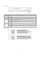
2.2 Front LEDs LED State POWER ON Description Wireless Access Point is powered on OP Flashing The Wireless Access Point is running well. PL Flashing Other PowerLine devices detected ON LAN Flashing TX or RX activity 1-4 WLAN Ethernet link is present at this port OFF Ethernet link is not present at this port ON Wireless function on Flashing Data transferring between this Wireless Access Point and wireless clients OFF Wireless function off 2.
Connector POWER Description Connect to power cord. Wireless Access Point is connected to a device through the corresponding port (1, 2, 3 or LAN (1-4) 4). While data is sending or receiving by that port, corresponding LED will be flashing. Antenna Two kinds of antenna connecter available: fixed or R/SMA connecter. 2.
Chapter 3 Configuration 3.1 Determine the type of your internet connection Before you configure the Wireless Access Point; you need to know the type of internet connection you’re using. You can ask your internet service provider to know the type of internet connection you’re using. 3.
11
You can use "Quick Setup" to setup the device, and choose the connection method you want to use.
3.3.1 LAN Interface Configuration Please input the IP address and network mask of LAN interface here..
3.4.1 Wireless Settings Wireless Mode You can select wireless operating mode here. Available options are: Auto (both 802.11b and 802.11g), 802.11b only, 802.11g only, and Disable (Wireless disabled) SSID SSID is the short for ‘Service Set IDentifier’. Wireless devices use this identifier to identify which access point they should connect. You can change SSID here, and all your wireless devices should set to the same SSID. Channel The radio channel number that wireless network uses.
3.4.2 Wireless Security You can select the wireless authentication method here. Available options are: ‘Open System’, ‘Shared Key’, ‘WPA-PSK’, ‘WPA2-PSK’, and ‘WPA-PSK/WPA2-PSK’.
3.4.3 Advanced Wireless Settings You can set some advanced wireless settings here. In most cases you don’t have to change these settings, and you can use default settings without any problem. Only change these settings when you understand the function of these functions. PLEASE NOTE:IMPRPOER VALUE FOR THESE SETTINGS COULD CAUSE PERFORMANCE PROBLEM.
3.4.4 MAC-based Wireless Access Control You can allow or reject wireless clients with certain MAC address to connect to Wireless Access Point. Please select a MAC ACL mode you wish to use (‘Disable’, ‘Allow’, or ‘Reject’), and input MAC address(es) you wish to allow (or reject) in every index field. An example of MAC address is aa-bb-cc-dd-ee-ff or 1a-2b-3c-4d-5e-6f.
3.5.1 System Setup 1) You can change the name of super user (administrator) account from admin to any name you wish to use by inputting a new name in ‘Account’ field. 2) If you downloaded latested firmware file from Edimax website, you can upload and update the firmware here. Click ‘browse’ to select firmware file you just downloaded, and click ‘Update’ to start update procedure.
3.6.1 TCP/IP Settings for Windows Operating System 1. How to check my IP Address in Windows 95, 98, or Me? ‧Click Start, then click Run. ‧The Run Dialogue Box will appear. Type winipcfg in the window as shown then click OK ‧The IP Configuration window will appear, displaying your Ethernet Adapter Information. ‧Select your network adapter from the drop down menu. ‧If you can not see your network adapter in the drop down menu, your adapter may not properly installed.
2. How to check my IP Address in Windows 2000/XP? ‧Click Start, then click Run. ‧Type cmd then click OK. ‧From the command prompt, type ipconfig. It will return with your IP Address, subnet mask, and default gateway information. ‧Type exit to close the command prompt. ‧Please check the IP address of default gateway. It should be the address of Wireless Access Point. By default, the IP address of Wireless Access Point is 192.168.2.1.
3. How can I assign a Static IP Address in Windows 98/Me? ‧From the desktop, right-click on the Network Neighborhood icon (Win ME - My Network Places) and click Properties. ‧Highlight TCP/IP and click the Properties button. If you have more than 1 adapter, then there will be a ’TCP/IP Binding’ for each adapter. Highlight TCP/IP > (your network adapter) and then click Properties.
‧Click Specify an IP Address. ‧Enter in an IP Address that is on the same subnet of your Wireless Access Point. Example: If the Wireless Access Point’s LAN IP Address is 192.168.2.1, make your IP Address 192.168.2.X where X is a value between 2 to 99. Make sure that the number you choose is not in use on the network. ‧Click Gateway tab. ‧ Enter the LAN IP Address of your Wireless Access Point here (192.168.2.1), then click ‘Add’. ‧ Click ‘OK’.
‧Click DNS Configuration tab. ‧Click Enable DNS. Type in a Host (can be anything like John or Apple). For ‘DNS server search order’ field, enter the IP Address of your Wireless Access Point (192.168.2.1), then click Add.
‧Click OK once, then click OK again in next dialogue box. ‧When you’re prompted to reboot your computer, click Yes. After the computer is rebooted, the computer will have a static private IP Address.
4. How can I assign a Static IP Address in Windows 2000? ‧Right-click on My Network Places then click Properties. ‧Right-click on the Local Area Connection which represents your network card and select Properties. ‧Highlight Internet Protocol (TCP/IP) and click Properties.
‧Click Use the following IP Address and enter an IP Address that is on the same subnet of your Wireless Access Point. Example: If the Wireless Access Point´s LAN IP Address is 192.168.2.1, make your IP Address 192.168.2.X where the value of X is 2 to 99. Make sure that the number you choose is not in use on the network. ‧Set the Default gateway to the IP Address of your Wireless Access Point (192.168.2.1). ‧Set the Primary DNS to the IP address of your Wireless Access Point (192.168.2.1).
‧Launch your Web browser and enter the IP Address of your Wireless Access Point in the address bar. You should be able to see the login page of Wireless Access Point. Input administrator account and password to login.
Chapter 4. Network Utility for PowerLine Access Point Note: The device is able to detect other powerline devices which is on the same power circuit automatically. You only need to install.this utility program when you want to enable the encrypt function of Powerline Access Point to secure your data, or you have problem connecting other powerline devices.
4.2 Windows Configuration Utility In order to run the utility, double-click the utility icon. Figure 2 shows the content of main tab of the configuration utility. The following picture shows a Powerline Ethernet device connected as a local device and other Powerline Ethernet devices as remote devices.
Figure 3 : Main tab with local low-speed Powerline Ethernet device 4.3 User Interface 4.3.1 The ‘Main’ Tab The Main tab provides a list of all Powerline Ethernet devices logically connected to the computer where the configuration utility is running. The top panel shows all local Powerline Ethernet devices found. In most cases, only one device will be shown there.
Figure 4: Multiple local devices found 31
The lower panel displays all the Powerline Ethernet devices, discovered on the current logical network (remote devices). The number of remote devices found, the type of logical network (Public or Private), and a message area that reports connectivity and scan status will be displayed above this panel. The following information is displayed for each devices found: Device Name column shows the name of a found device. You can click on the name or click ‘Rename’ to change the name of a selected device.
The Add button is used to add a remote device to your network that is not listed in the lower panel, for example, a device currently located on another logical network. Users will be prompted to input the passwords for all devices they wish to manage and add them to the local logical network by clicking on the Add button. A dialog box will appear as shown below. The dialog box allows user to enter both device name and the password.
Figure 7: Main tab of the configuration utility 4.3.2 The ‘Privacy’ Tab The Privacy dialog screen provides a means for managing the local network and providing additional security. All Powerline Ethernet devices come with a default logical network (network name), which is normally “HomePlug” . The Privacy tab allows user to make the network private by changing the network name (network password) of devices.
Figure 8: Privacy tab The Set Local Device Only button is used to change the network name (network password) for local devices only. After doing this, all the devices seen on the Main panel prior to this will no longer reachable or respond to your command, as they will be located n a different logical network hereafter. Devices previously set up with the same logical network (same network name) will appear in the device list afterward by selecting this option.
‧ Operating System Type/Version ‧ Host Network Name ‧ User Name ‧ MAC Address of all NICs (network interface card) ‧ Identify versions of all Driver DLLs and Libraries used (NDIS) and optionally ‧ Powerline Ethernet device chipset manufacturer name (85Mbps version Only) ‧ MAC Firmware Version (85Mbps version Only) ‧ Vendor name Figure 9: Diagnostics Screen The lower panel contains a history of all remote devices found by the computer.
‧ Adapter Last known rate ‧ Adapter Last Known Network ‧ HomePlug chipset manufacturer name ‧ Data devices found lately ‧ MAC Firmware Version (85Mbps version Only) The diagnostics information displayed may be saved to a text file for later emailing to technical support of a manufacturer, or printed for reference during a technical support call. Devices no longer part of the network can be deleted using the delete button. 4.4.1 About tab This tab shows the software release date.
4.5 Troubleshooting This section will introduce how to solve the problem for managing remote Powerline devices. 4.5.1 Having problem with connecting remote PowerLine Access Point device When you found that the computer is unable to connect to another or the remote Powerline device can not found by Powerline utility, please follow the following steps to solve the problem. Step 1: Launch the utility to check you can access the device or not.
Step 2: Connect to the other Powerline bridge or Wireless Access Point directly which can not be detected in last step 1. On the Privacy tab, you can change the Private Network name as the same name of other Powerline device or click the Use Default (Public Network) button. Please click the Set Local Device Only button to change the network name. Please make sure the Private Network Name value must the same with the other Powerline devices.
Appendix A Glossary Address mask A bit mask used to select bits from a set of IP address for subnet addressing. The mask is 32 bits long and network devices uses these bits to identify which bits in an IP address are network number, and which bits are hosy number. Address mask is also known as subnet mask. AAL5 ATM Adaptation Layer 5 - This layer maps higher layer user data into ATM cells, making the data suitable for transport through the ATM network. ADSL Asymmetric digital subscriber line.
CPE Customer Premises Equipment located in a user's premises. DHCP (Dynamic Host Configuration Protocol) DHCP is a mechanism that automatically assigns IP addresses to client stations logging onto a TCP/IP network. DHCP eliminates the load of manually assign permanent IP addresses to every device on your network. DHCP software typically runs on servers and also can be found in network devices such as Wireless Access Points.
Hop count A measurement for the distance between two hosts on the network. It is equivalent to the number of routers that separate the source and destination. HTML Hypertext Markup Language - The page-coding language for the World Wide Web. HTML browser A browser is a program used to explore the Internet, such as Netscape or Microsoft Internet Explorer. http Hypertext Transfer Protocol - The protocol used to carry world-wide-web (www) traffic between a www client and the www server.
media control. MIB Management Information Base - A collection of objects can be accessed via a network management protocol, such as SNMP and CMIP (Common Management Information Protocol). NAT Network Address Translation - A proposal for IP address reuse, where the local IP address is mapped to a globally unique address.
Route The path that network traffic takes from its source to its destination. The route that a datagram passes by may include many routers and many physical networks. In the Internet, each datagram is routed separately. Router A system responsible for making decisions about which of several paths network (or Internet) traffic will follow. To do this, it uses a routing protocol to gain information about the network and algorithms to choose the best route based on several criteria known as ‘routing metrics’.
Static IP Addresses A static IP address is an IP address permanently assigned to computer in a TCP/IP network. Static IP addresses are usually assigned to networked devices that are consistently accessed by multiple users, such as Server PCs, or printers. If you are using your Wireless Access Point to share your cable or DSL Internet connection, contact your ISP to see if they have assigned your home a static IP address. You will need that address during your Wireless Access Point's configuration process.
Virtual Connection (VC) A link that seems and behaves like a dedicated point-to-point line or a system that delivers packets in sequence, as happens on an actual point-to-point network. In reality, the data is delivered across a network via the most appropriate route. The sending and receiving devices do not have to be aware of the options and the route is chosen only when a message is sent. There is no pre-arrangement, so each virtual connection exists only for the duration of that one transmission.
Appendix B Cabling / Connection Network cables connect PCs in an Ethernet network Category 5, called as ‘Cat5’ for short is commonly used type of network cable today. Cat 5 cables are tipped with RJ-45 connectors, which fit into RJ-45 port. Straight-through vs. Crossover Cables: Straight-through Straight-through Wire Becomes Wire Becomes 1 1 1 1 2 2 2 2 3 3 3 3 6 6 6 6 LAN Connection: Check if LEDs are illuminated when you finish connecting two pieces of hardware.
Declaration of Conformity The following Equipment: Powerline 85M Wireless-G Access Point Report No.: S940111 is herewith confirmed to comply with the requirements set out in the Council Directive on the harmonization of the Laws of the Member States relating to electrical equipment designed for use within certain voltage limits (73/23/EEC).