Load Balancing Router User’s Guide
TABLE OF CONTENTS 1: INTRODUCTION ................................................................................................................................ 1 Internet Features ............................................................................................................................ 1 Other Features ................................................................................................................................ 3 Package Contents .......................................
9: OPERATION AND STATUS ........................................................................................................... 63 Operation....................................................................................................................................... 63 System Status............................................................................................................................... 63 WAN Status ..........................................................................
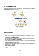
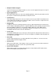
1: Introduction Congratulations on the purchase of your new Load Balancer. The Load Balancer provides Shared Broadband Internet Access for all LAN users. Figure 1-1: Load Balancer Internet Features • Shared Broadband Internet Access All LAN users can access the Internet through the Load Balancer, by sharing one (1) or two (2) Broadband modems and connections. • High-Performance Dual Modem Support The Load Balancer has two (2) WAN ports, allowing connection of two (2) Broadband modems.
• Multiple IP Address Support If your ISP allocates you multiple IP addresses, these are also supported and you can “map” IP addresses to individual PCs if desired. • Special Applications This feature allows you to use some non-standard applications, where the port number used for the response is different to the port number used by the sender. • Virtual Servers This feature allows Internet users to access Internet servers on your LAN.
Other Features • 4-Port Switching Hub The Load Balancer incorporates a 4-port 10 /100BaseT switching hub, making it easy to create or extend your LAN. • DHCP Server Support Dynamic Host Configuration Protocol provides a dynamic IP address to PCs and other devices upon request. The Load Balancer can act as a DHCP Server for devices on your local LAN. • Multi Segment LAN Support LANs containing one or more segments are supported, via The Load Balancer's built-in static routing table.
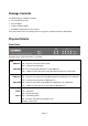
Package Contents The following items should be included: • The Load Balancer Unit • Power Adapter • Quick Installation Guide • CD-ROM containing the on-line manual. If any of the above items are damaged or missing, please contact your dealer immediately. Physical Details Front Panel Operation of the Front Panel LEDs is as follows: LAN LINK/ACT ON – Physical connection or data in/out. OFF – No physical connection. 10M/100M ON – The corresponding LAN port is using 100BaseT.
Also, some Status and Error conditions are indicated by combinations of LEDs, as shown below LED Action Condition WAN1 LINK/ACT & 10M/100M LEDs flash alternatively. Firmware Download in progress. WAN1 LINK/ACT & 10M/100M LEDs flash concurrently. MAC address not assigned.
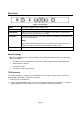
Rear Panel Figure 1-2: Rear Panel DC 5V Connect the supplied power adapter here. WAN 2 Connect the 2nd Broadband Modem here, if available. Reset Button When pressed and released, The Load Balancer will reboot (restart) within 1 second. It resets to default over 3 seconds. LAN Ports Connect the PCs to these ports. Both 10BaseT and 100BaseT connections can be used simultaneously. Note: Any port will automatically operate as an "Uplink" port if required.
Figure 1-3: Windows TFTP utility • Enter the name of the firmware upgrade file on your PC, or click the "Browse" button to locate the file. • Enter the LAN IP address of The Load Balancer in the "Server IP" field. • Click "Download" to send the file to The Load Balancer. 3. When downloading is finished. It should then work normally, using the default settings.
2: Basic Setup Overview Basic Setup of your Load Balancer involves the following steps: 1. Attach The Load Balancer to one (1) PC, and configure it for your LAN. 2. Install your Load Balancer in your LAN, and connect the Broadband Modem or Modems. 3. Configure your Load Balancer for Internet Access. 4. Configure PCs on your LAN to use The Load Balancer. Requirements • One (1) or two (2) DSL or Cable modems, each with an Internet Access account with an ISP. • Network cables.
• You can and should set a password, using the following Admin Password screen. No Response ? • Is your PC using a Fixed IP address ? If so, you must configure your PC to use an IP address within the range 192.168.1.2 to 192.168.1.254, with a Network Mask of 255.255.255.0. See Appendix B – Windows TCP/IP Setup for details. • Check that The Load Balancer is properly installed, LAN connection is OK, and it is powered ON. 8. After the login, you will then see the Admin Password screen, as shown below.
9. Select LAN & DHCP from the menu. You will see a screen like the example below. Figure 2-3: LAN & DHCP 10. Ensure these settings are suitable for your LAN: • The default settings are suitable for many situations. • See the following table for details of each setting. 11. Save your data, then go to Step 2, Installing The Load Balancer in your LAN. Settings – LAN & DHCP IP Address IP address for The Load Balancer, as seen from the local LAN.
DHCP IP Address Range ARP Proxy • DHCP Server Setup - If you are already using a DHCP Server, the DHCP Server setting must be Disabled, and the existing DHCP server must be set to provide the IP address of The Load Balancer as the Default Gateway. • Client Lease Time – It is a finite period of time for a DHCP server lease an IP address to a client.. • Client Default DNS – An IP address of the default DNS server for the client requesting DHCP service.
2. Installing The Load Balancer in your LAN Figure 2-4: Installation Diagram 1. Ensure The Load Balancer and the DSL/Cable modem are powered OFF. Leave the modem or modems connected to their data line. 2. Connect the Broadband modem or modems to The Load Balancer. • If using only one (1) Broadband modem, connect it to the "WAN 1" port. • Use the cable supplied with your DSL/Cable modem. If no cable was supplied, use a standard cable. 3.
• For each PC connected to the LAN ports, the corresponding LAN LED (either 10 or 100) should be ON. 3. Configuring The Load Balancer for Internet Access Select Primary Setup from the menu, to see a screen like the example below. • Configure WAN 1 and/or WAN 2 as required. • For any of the following situations, refer to Chapter 3: Advanced Port Setup for any further configuration, which may be required.
Settings – Primary Setup Connection Mode Connection Type Select the appropriate setting: • Enable – Select this if you have connected a broadband modem to this port. • Disable – Select this if there is no broadband modem connected to this port. • Backup – Use this if you have a broadband modem on each port, and wish to normally use only one. Select Enable for the primary port, and Backup for the secondary port. The Backup port will only be used if the primary port fails.
Optional • Host name – This is required by some ISPs. If your ISP provided a Host Name, enter it here. Otherwise, you can use the default value. • Domain name – This is required by some ISPs. If your ISP provided a Domain Name, enter it here. Otherwise, you can use the default value. • MAC address – Some ISP's record your MAC address (also called "Physical address" or "Network Adapter address"). If so, you can enter the MAC address expected by your ISP in this field.
4: Configure PCs on your LAN Overview For each PC, the following may need to be configured: • TCP/IP network settings • Internet Access configuration TCP/IP Settings If using the default Load Balancer settings, and the default Windows 95/98/ME/2000/XP TCP/IP settings, no changes need to be made. Just start (or restart) your PC. • By default, The Load Balancer will act as a DHCP Server, automatically providing a suitable IP Address (and related information) to each PC when the PC boots.
7. Select "Set up my connection manually" and click “Next”. 8. Check "Connect using a broadband connection that is always on" and click Next. 9. Click Finish to close the New Connection Wizard. Setup is now completed. Accessing AOL To access AOL (America On Line) through The Load Balancer, the AOL for Windows software must be configured to use TCP/IP network access, rather than a dial-up connection. The configuration process is as follows: • Start the AOL for Windows communication software.
• Set your Default Gateway to the IP Address of The Load Balancer. • Ensure your DNS (Name server) settings are correct. To act as a DHCP Client (recommended) The procedure below may vary according to your version of Linux and X -windows shell. 1. Start your X Windows client. 2. Select Control Panel - Network 3. Select the "Interface" entry for your Network card. Normally, this will be called "eth0". 4. Click the Edit button, set the "protocol" to "DHCP", and save this data. 5.
3: Advanced Port Setup Overview • Port Options contains some options, which can be set on either or both WAN ports. For most situations, the default values are satisfactory. • Load Balance screen is only functional if you are using both WAN ports. It allows you to determine the proportion of WAN traffic sent through each port. • Advanced PPPoE setup is required if you wish to use multiple sessions on one or both of the WAN ports. It can also be used to manually connect or disconnect a PPPoE session.
Settings – Port Options Connection Validation PPPoE / PPTP Connection Options Transparent Bridge • Health Check – Disable will not do Alive Indicator Check. By default health check is enable. Health checking is performing an ICMP echo request and HTTP packets to the specific destination that could be either: 1. Name or IP Address user specified in the “Alive Indicator” input box or gateway of WAN interface if “Alive Indicator” input box is left blank.
Load Balance This screen is only operational if using Internet connections on both WAN ports. Figure 3-2: Load Balance These settings are only functional if using both WAN ports. If using both WAN ports, these settings determine the proportion of traffic sent over each port.
Settings – Load Balance Load Balance Configuration • Enable – Use this to enable your Load Balance settings. Unless this is checked, the other settings on this screen have no effect. • Balance Type – Select the desired option: • • Bytes rx+tx – Traffic is measured by Bytes. • Packets rx+tx – Traffic is measured by Packets. • Sessions established – Traffic is measured by Sessions. • IP Address – Traffic is measured by IP address.
Advanced PPPoE The screen is required in order to use multiple PPPoE sessions on the same WAN port. It can also be used to manually connect or disconnect a PPPoE session. Figure 4: Advanced PPPoE Settings – Advanced PPPoE WAN Port PPPoE Session Select the desired Port and Session, then click the "Select" button. The data for the selected Port/Session will then be displayed in the WAN IP Account section. Session MTU The Maximum Transfer Unit for PPPoE packet data.
Advanced PPTP This screen is only useful if using the PPTP connection method. Figure 5: Advanced PPTP Settings – Advanced PPTP WAN Port Select the desired Port, then click the "Select" button. The data for the selected Port will then be displayed in the WAN IP Account section. WAN IP Account • User Name – The PPTP user name (login name) assigned by your ISP. • Password – The PPTP password associated with the User Name above. This is assigned by your ISP, and used to login to the PPTP Server.
4: Advanced Configuration Overview The following advanced features are provided. • Host IP Setup • Virtual Servers • Custom Virtual Server • Special Applications • Dynamic DNS • Multi DMZ • Advanced Features • UPnP This chapter contains details of the configuration and use of each of these features. Host IP Setup This feature is used in the following situations: • You have Multi-Session PPPoE, and wish to bind each session to a particular PC on your LAN.
Figure 4-1: Host IP Setup Settings – Host IP Setup Host Network Identity This section identifies each Host (PC) • Host List – When adding a new Host, ignore this list. To edit an existing entry, select it from the list, and click the "Select" button. The data fields will then be updated with data for the selected entry. • Host name – Enter a suitable name. Generally, you should use the "Hostname" (computer name) defined on the Host itself.
Host Network Binding • Bind WAN port/Session – Select Enable if you wish to associate this PC with a particular PPPoE Session. All traffic for that PC will then use the selected PPPoE port and session. • Binding Method – Suppose your PC is bound to WAN1 port, now you are selecting “Strict Binding”. If WAN1 port is disconnected, your packets cannot go out through WAN2 port, if WAN2 port is still alive.
Virtual Servers This feature allows you to make Servers on your LAN accessible to Internet users. Normally, Internet users would not be able to access a server on your LAN because: • Your Server's IP address is only valid on your LAN, not on the Internet. • Attempts to connect to devices on your LAN are blocked by the firewall in The Load Balancer. The "Virtual Server" feature solves these problems and allows Internet users to connect to your servers, as illustrated below.
Figure 4-3: Virtual Server Settings – Virtual Server Enable Use this to Enable or Disable each Virtual server as required. Server Type Select the desired Server type. If the type of Server you wish to use is not listed, use the Custom Virtual Server screen to define your own type. LAN IP Address Enter the IP address of the PC on your LAN which is running the required Server software. Each PC should have a fixed IP address, or have a reserved IP address.
Custom Virtual Servers This screen allows you to define your own Server types, for situations when the desired Server type is not listed on the Virtual Servers screen. Figure 4-4: Custom Virtual Servers Settings – Custom Virtual Servers Select Custom Server Name Server List If creating a new entry, ignore this list. To edit an existing entry, select it, and then click the "Select" button. The screen will update with data for the selected entry.
Buttons Custom Virtual Server List • Protocol Type – Select the network protocol used by this sever type. • LAN Port Range – Enter the range of port number used for outgoing traffic from this Server. If only a single port is required, enter it in both fields. • WAN Port Range - – Enter the range of port number used for incoming traffic to this Server.
Special Applications If you use Internet applications which have non-standard connections or port numbers, you may find that they do not function correctly because they are blocked by the firewall in The Load Balancer. In this case, you can define the application as a "Special Application" in order to make it work.
Outgoing Port Range Enter the beginning and end of the range of port numbers used by the application server, for data you send. If the application uses a single port number, enter it in both fields. Incoming Protocol Select the protocol used by this application, when receiving data from the remote server or PC. Incoming Port Range Enter the beginning and end of the range of port numbers used by the application server, for data you receive.
Dynamic DNS Dynamic DNS is very useful when combined with the Virtual Server feature. It allows Internet users to connect to your Virtual Servers using a URL, rather than an IP Address. This also solves the problem of having a dynamic IP address. With a dynamic IP address, your IP address may change whenever you connect to your ISP, which makes it difficult to connect to you. You must register for the Dynamic DNS service.
Settings – Dynamic DNS Dynamic DNS Service Use this to Enable/Disable the Dynamic DNS feature, and select the required service provider. • Disable – Dynamic DNS is not used. • TZO – Select this to use the TZO service (www.tzo.com). You must configure the TZO section of this screen. • Standard Client – Select this to use the standard service (from www.dyndns.org or other provider). You must configure the Standard Client section of this screen. • 3322(in China) – This is available in China.
Multi DMZ This feature allows each WAN port IP address to be associated with one (1) computer on your LAN. All outgoing traffic from that PC will be associated with that WAN port IP address. Any traffic sent to that IP address will be forwarded to the specified PC, allowing unrestricted 2-way communication between the "DMZ PC" and other Internet users or Servers. Note: The "DMZ PC" is effectively outside the Firewall, making it more vulnerable to attacks.
Settings – Multi DMZ Use this to enable or disable the DMZ setting, as required. Enable Name Enter a name to assist you to remember this setting. This name has no effect on the operation. For Static IP Public IP address Enter the WAN port (Internet) IP address you wish to associate to a PC. This IP address must have been allocated to you by your ISP. Private IP Address (LAN) Enter the IP address of the PC you wish to associate with this WAN port IP address.
UPnP With UPNP (Universal Plug & Play) function, it can easily setup and configure an entire network, enable discovery and control of networked devices and services. Figure 4-8: UPnP Settings – UPnP UPnP Option If you Enable UPnP, then this two wan router will become one of the entire local network. You can find out there is an icon show up on network neighborhood on the window XP OS. Every time you add a new network device with port mapping, The new network device will appear on the mapping list.
NAT NAT (Network Address Translation) is the technology which allows one (1) WAN (Internet) IP address to be used by many LAN users.
Settings – NAT NAT Configuration NAT Alias • NAT Routing – You can enable or disable NAT through the check box. If you disable NAT checkbox, it will act as a bridge or Static Router. Most features will be unavailable. • TCP Timeout – Enter the desired value to use on both WAN ports. The default is 300. • UDP Timeout – Enter the desired value to use on both WAN ports. The default is 120. • TCP Window Limit – Enter the desired value to use on both WAN ports. The default is 0 (no limit).
Advanced Features This screen allows you to change some advanced settings: • Remote Access Configuration – This feature allows you to manage The Load Balancer via the Internet. You can restrict access to a specified IP address or address range. • External Filters Configuration – These settings determine whether or not The Load Balancer should respond to ICMP (ping) requests received from the WAN port.
Settings – Advanced Features Remote Access Configuration • Remote Upgrade – If enabled, you can use the supplied Windows program to remotely upgrade the Firmware. If not enabled, upgrades must be performed by a PC on the LAN. • Remote Web-based setup - – If enabled, access to the Web-based interface is available via the Internet. (See below for details.) If not enabled, access is only available to PCs on the LAN. • Port – The port number used when connecting remotely. See below for details.
Interface Binding SMTP (Simple Mail Transport Protocol) Binding Unless you are using E-mail accounts from different ISPs on each port, you can ignore these settings. Some ISPs configure their E-mail Servers so they will not accept E-mail from IP addresses not allocated by themselves. If you are using accounts from different ISPs, sending E-mail over the wrong port may result in non-acceptance of the mail. In this case, you can use these settings to correct the problem.
5: Security Management Overview • URL Filter It can block specific or browse only certain website by configure IP address, URL or Key words • Access filter You can block all Internet access or select block well-known port or block user define ports by groups. • Session Limit It can eliminate users access Internet, and send email alert to the administrator. If the device detect new sessions that is exceed the maximum sampling time.
Settings – URL Filter Access Group Block Internet Access This allows you have different blocking rules for different Groups of PCs. • All PCs (users) are in the Default Group unless moved to another group on the Host IP screen. • If you want the same restrictions to apply to everyone, select Default for the Group. In this case, there is no need to enter any Hosts on the Host IP screen.
Access Filter The network Administrator can use the Access Filter to gain fine control over the Internet access and applications available to LAN users. • Five (5) user groups are available, and each group can have different access rights. • All PCs (users) are in the Default group, unless assigned to another group on the Host IP screen. Figure 5-2: Access Filter Settings – Access Filter Setup Access Group Filter Setting This allows you have different access rights for different Groups of PCs.
Block Well-known ports Select the services you wish to block. The current group will not be able to use any services which are checked. User-defined Ports to Block This section is optional. It allows you to define your own filters if required. For each filter, the following information is required. • Name – Enter a meaningful name for this filter. • TPC/UDP Packets – Select either TCP or UDP, depending on which protocol is used by the service you wish to block. • Port No.
Session Limit This new feature allows to drop the new sessions from both WAN and LAN side. If the new sessions number are exceed the maximum sessions in a sampling time. Figure 5-3: Session Limit Session Limit Sampling Time The period to count the new session. Only those new sessions occurred in the most recently sampling time were be count for limit checking.(Default is 400 mil-sec) Maximum of Total New session If the number of new sessions for system exceed the maximum in the Sampling Time.
System Filter Exception System Filter Exception Rules: The rules with which any received packets is complied, the packets will not processed by Firewall or NAT module, but to be processed directly by system protocol stack. Figure 5-4: System Filter Exception Firewall Exception Enable The check box can allow you enable or disable firewall exception. Interface You can select LAN, WAN1, WAN2 or ALL interfaces to be process by the system protocol stack. If you enable check box.
6: QoS Configuration Overview The Load Balancer provides QoS, which supports the high quality of network service. Because it will classify outgoing packets based on some policies defined by users, make some real-time applications to get better response or performance. QoS Setup The following web page management are guiding you how to setup QoS and make QoS work. Figure 6-1:QoS Setup Data – QoS Setup.
Policy Configuration When you use QoS, you must define some policies to make some packets to have higher priority to pass through. Figure 6-2: Policy Configuration Data – Policy Configuration. Network Admission Policy This section identifies each policy • Policy Name List – When adding a new Policy, ignore this list. To edit an existing entry, select it from the list, and click the "Select" button. The data fields will then be updated with data for the selected entry.
7: Management Assistant Overview The following advanced features are provided. • SNMP • Email Alert • SNMP • Syslog • Upgrade Firmware This chapter contains details of the configuration and use of each of these features. SNMP This section is only useful if you have SNMP (Simple Network Management Protocol) software on your PC. If you have SNMP software, you can use a standard MIB II file with The Load Balancer.
Settings – SNMP System Information Trap Targets • Contact Person – The name of the person responsible for this device. • Device name – The name of The Load Balancer. • Physical Location – The location of The Load Balancer. Enter the IP address of any targets (PCs running SNMP software) to which you want traps to be sent. All traps are level 1. Email Alert This feature will send an warning Email, inform system administrator that one of the WAN ports was disconnected.
Settings – Email Alert Enable/Disable Email Alert • Enable – This will enable email alert to send a warning email when WAN port was disconnected. Email Alert Configuration • Sender Address – It is an email address that sends a warning email to a recipient. • Recipient Address –It is an email address a warning email will be sent to. Usually it is system administrator email address. For example: admin@mail.domain.
Syslog This feature can send real time system information on the web page or to the specified PC. Syslog Configuration – Syslog Configuration allow you where to send system information to other machine or not. There are up to three machines you can choose to send your system log. Message Status– Messages send only keep when “keep send message” checked. Currently we keep last 100 messages in the RAM area, they will clear when reboot or power off.
Syslog Configuration Syslog Global • Enable – Set to “enable”, if you want to send system log messages to other machine. Keep Sent Messages • Enable – Checked this, if you want to keep sent messages, otherwise the sent messages will be deleted. Syslog Server • IP address: Up to 3 syslog servers can be used. • Enable: You can enable or disable each server temporarily. • Port: If your syslog server does not use the default port, you can change it.
Admin Password Screen The password screen allows you to assign a password to The Load Balancer. Figure 7-4: Admin Password Screen Enter the desired password, re-enter it in the Verify Password field, then save it. When you connect to The Load Balancer with your Browser, you will be prompted for the password when you connect, as shown below. Figure 7-5: Password Dialog • Enter "Admin" for the User Name. • Enter the password for The Load Balancer, as set on the Admin Password screen above.
Upgrade Firmware This Upgrade Firmware Screen allows you to upgrade firmware or backup system configuration by using HTTP upgrade. Figure 7-6: Firmware Upgrade Screen You can backup your system configuration by press “save” button of Save System Configuration. It will save the system configuration for you. (Notice: You have to refresh the browser after you saved the system configuration file) You also can do firmware upgrade by input the correct password and the file name of your firmware.
8: Advanced LAN Configuration Overview These screens and settings are provided to deal with non-standard situations, or to provide additional options for advanced users. Existing DHCP Server If your LAN already has a DHCP Server, and you wish to continue using it, the following configuration is required. • The DHCP Server function in The Load Balancer must be disabled. This setting is on the LAN & DHCP screen.
Figure 8-1: Routing Note: If there is an entry or entries in the Routing table with an Index of zero (0), these are System entries. You cannot modify or delete these entries. Settings – Routing Dynamic Routing Entry Index • RIP v2 – This acts as “master” switch. If enabled, the selected WAN or LAN will run RIPv1/v2, otherwise they don’t have RIP function. • LAN, WAN1, WAN2 – If enabled, any WAN or LAN can execute RIP function. • • If adding a new entry, ignore this field.
Gateway The IP Address of the Gateway or Router that The Load Balancer must use to communicate with the destination above. (NOT the router attached to the remote segment.) Interface Select the correct interface, usually "LAN". The "WAN" interface is only available if NAT (Network Address Translation) is disabled. Metric The number of "hops" (routers) to pass through to reach the remote LAN segment. The shortest path will be used.
Gateway IP Address 192.168.1.100 Interface LAN Metric 2 Entry 2 (Segment 2) Destination IP Address 192.168.3.0 Network Mask 255.255.255.0 (Standard Class C) Gateway IP Address 192.168.1.100 Interface LAN Metric 3 For Router A's Default Route Destination IP Address 0.0.0.0 Network Mask 0.0.0.0 Gateway IP Address 192.168.1.1 Metric 2 For Router B's Default Route Destination IP Address 0.0.0.0 Network Mask 0.0.0.0 Gateway IP Address 192.168.2.
9: Operation and Status Operation Once both The Load Balancer and the PCs are configured, operation is automatic. However, there are some situations where additional Internet configuration may be required: Refer to Chapter 4 - Advanced Features for further details. System Status Use the System Status link on the main menu to view this screen.
Data – System Status WAN Information LAN Information Device Information Device Statistics • Connection Status – Current status – either "Connected" or "Not connected". • Connection Type – The type of connection used – DHCP, Fixed IP, PPPoE, or PPTP. • "Force Renew" button– Only available if using a dynamic IP address (DHCP). Clicking this button will perform a DHCP "Renew" transaction with the ISP's DHCP server. This will extend the period for which the current WAN IP address is allocated to you.
Buttons • Refresh – Update the data on screen. • Restart – Restart (reboot) The Load Balancer. • Restore Factory Defaults – This will delete all existing settings, and restore the factory default settings. See below for details. Restore Factory Defaults When the "Restore Factory Defaults" button on the Status screen above is clicked, the following screen is displayed.
WAN Status Use the WAN Status link on the main menu to view this screen. Figure 9-3: WAN Status Data – System Status NAT Statistics Interface Statistics This section displays data for each WAN port. • Connection status – This will display either Connected or Not Connected. • Default Loading Share - The default traffic loading between the WAN ports. • Current Loading Share – The current traffic loading between the WAN ports.
NAT Status This screen is displayed when you click the "Check NAT Detail" button on the WAN Status screen. Figure 9-4: NAT Status Data – NAT Status LAN IP Info Active WAN IP Info NAT Timeouts • IP Address – The LAN IP Address of The Load Balancer. • Mask Address – The Network Mask (Subnet Mask) for the IP Address above. There is one (1) row for each active connection. For each connection, the following data is shown. • IP Address – The WAN (Internet) IP Address of The Load Balancer.
TCP Prosperity This displays the MSS (Maximum Segment Size) and Maximum Windows size for TCP packets. NAT Traffic This section displays statistics for both outgoing (LAN to Internet) and Incoming (Internet to Local) traffic. NAT Connections This displays the current number of active connections. For further details, click the "View Connection" list button. Errors Statistics are displayed for Checksum errors, number of retries, and number of bad packets. Misc.
Appendix A Specifications Model BR-6624 Dimensions 245mm (W) x 137mm (D) x 30mm (H) Operating Temperature 0° C to 40° C Storage Temperature -10° C to 70° C Network Protocol: TCP/IP Network Interface: 6 Ethernet: 4 * 10/100BaseT (RJ45) auto-Switching Hub ports for LAN devices 2 * 10/100BaseT (RJ45) for WAN LEDs 8 LAN 4 WAN 1 Status 1 Power External Power Adapter 5 V 1.5A DC FCC Statement This device complies with Part 15 of the FCC Rules.
Appendix B Windows TCP/IP Setup Overview TCP/IP Settings If using the default Load Balancer settings, and the default Windows 95/98/ME/2000 TCP/IP settings, no changes need to be made. • By default, The Load Balancer will act as a DHCP Server, automatically providing a suitable IP Address (and related information) to each PC when the PC boots. • For all non-Server versions of Windows, the default TCP/IP setting is to act as a DHCP client.
Figure B-2: IP Address (Win 95) Ensure your TCP/IP settings are correct, as follows: Using DHCP To use DHCP, select the radio button Obtain an IP Address automatically. This is the default Windows settings. Restart your PC to ensure it obtains an IP Address from The Load Balancer.
• On the DNS Configuration tab, ensure Enable DNS is selected. If the DNS Server Search Order list is empty, enter the DNS address provided by your ISP in the fields beside the Add button, then click Add. Figure B-4: DNS Tab (Win 95/98) Checking TCP/IP Settings - Windows 2000: 1. Select Control Panel - Network and Dial-up Connection. 2. Right click the Local Area Connection icon and select Properties. You should see a screen like the following: Figure B-5: Network Configuration (Win 2000) 3.
Figure B-6: TCP/IP Properties (Win 2000) 5. Ensure your TCP/IP settings are correct: Using DHCP To use DHCP, select the radio button Obtain an IP Address automatically. This is the default Windows settings. Restart your PC to ensure it obtains an IP Address from The Load Balancer.
Checking TCP/IP Settings - Windows XP: 1. Select Control Panel - Network Connection. 2. Right click the Local Area Connection and choose Properties. You should see a screen like the following: Figure B-7: Network Configuration (Windows XP) 3. Select the TCP/IP protocol for your network card. 4. Click on the Properties button. You should then see a screen like the following.
Figure B-8: TCP/IP Properties (Windows XP) 5. Ensure your TCP/IP settings are correct. Using DHCP To use DHCP, select the radio button obtain an IP Address automatically. This is the default Windows settings. Restart your PC to ensure it obtains an IP Address from The Load Balancer. Using a fixed IP Address ("Use the following IP Address") If your PC is already configured, check with your network administrator before making the following changes.
Appendix C Troubleshooting Overview This chapter covers some common problems that may be encountered while using The Load Balancer and some possible solutions to them. If you follow the suggested steps and The Load Balancer still does not function properly, contact your dealer for further advice. General Problems Problem 1: Can't connect to The Load Balancer to configure it. Solution 1: Check the following: • The Load Balancer is properly installed, LAN connections are OK, and it is powered ON.
Solution 2: The Load Balancer processes the data passing through it, so it is not transparent. Use the Special Applications feature to allow the use of Internet applications which do not function correctly. If this does solve the problem you can use the DMZ function. This should work with most applications, but: • It is a security risk, since the firewall is disabled for the DMZ PC. • Only one (1) PC can use this feature.