BR-6228nS V2 BR-6228nC V2 User Manual 09‐2013 / v1.
CONTENTS I. Product Information ............................................................................... 1 I‐1. I‐2. I‐3. I‐4. Package Contents .......................................................................................................... 1 LED Status ...................................................................................................................... 1 Back Panel ............................................................................................................
III‐3‐6. III‐3‐6‐1. III‐3‐6‐2. III‐3‐6‐3. III‐3‐6‐4. III‐3‐7. III‐3‐7‐1. III‐3‐8. III‐3‐8‐1. III‐3‐8‐2. III‐3‐8‐3. III‐3‐8‐4. III‐3‐8‐5. III‐3‐8‐6. III‐3‐8‐7. III‐3‐9. III‐3‐9‐1. III‐3‐9‐2. III‐3‐9‐3. III‐3‐9‐4. III‐3‐9‐5. III‐3‐9‐6. III‐3‐9‐7. III‐3‐9‐8. III‐3‐9‐9. Firewall......................................................................................................................... 57 URL Blocking ..................................................................................................
IV‐1‐3‐2. IV‐1‐4. IV‐1‐4‐1. IV‐1‐4‐2. IV‐1‐4‐3. IV‐2. IV‐3. IV‐4. Mac ............................................................................................................................112 How to Find Your Router’s IP Address .......................................................................115 Windows XP, Vista & 7...............................................................................................115 Windows 8 .......................................................................
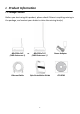
I. Product Information I‐1.
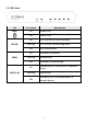
I‐2. LED Status LED PWR WLAN WAN LAN (1–4) LED Status Description On Device is on. Off Device is off. On Wi‐Fi is active (or WPS is active). Flashing Wi‐Fi activity (transferring data). Off Wi‐Fi is not active. On WAN port connected. Flashing WAN activity. Off WAN port not connected. On Ethernet port is connected to a network device. Flashing Off LAN activity. Ethernet port is not connected to a network device.
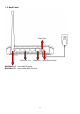
I‐3.
I‐4. Safety Information In order to ensure the safe operation of the device and its users, please read and act in accordance with the following safety instructions. 1. The device is designed for indoor use only; do not place it outdoors. 2. Do not place the device in or near hot/humid places, such as a kitchen or bathroom. 3. Do not pull any connected cable with force; carefully disconnect it from the BR‐6228nS V2/nC V2. 4. Handle the device with care. Accidental damage will void the warranty of the device.
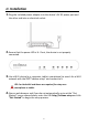
II. Installation 1. Plug the included power adapter into the device’s 5V DC power port and the other end into an electrical socket. 2. Ensure that the power LED is lit. If not, the device is not properly connected. 3. Use a Wi‐Fi device (e.g. computer, tablet, smartphone) to search for a Wi‐Fi network with the SSID “edimax.setup” and connect to it. iOS 4 or Android 4 and above are required for setup on a smartphone or tablet. 4.
If you cannot access http://edimax.setup, please make sure your computer is set to use a dynamic IP address. Refer to IV‐1. Configuring your IP address for more information. 5. Select the mode for your BR‐6228nS V2/nC V2 and click “Next” to continue. Wi‐Fi Router Access Point The device connects to your modem and enables Internet (wireless and Ethernet) access on your network devices.
and Ethernet) access for your network devices. Range Extender The device connects wirelessly to your existing network and repeats the wireless signal.
II‐1. Wi‐Fi Router Mode 1. Connect the blue WAN port of your BR‐6228nS V2/nC V2 to the LAN port of your modem using an Ethernet cable, and then click “Next”. 2. Please wait a moment while the BR‐6228nS V2/nC V2 tests the connection.
3. 4. Click “Next” to continue and configure the device’s wireless network. Enter a name and password for your wireless network, then click “Next” to continue.
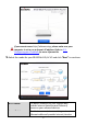
5. A summary of your configuration will be displayed, as shown below. Check that all of the details are correct and then click “Next” to proceed. If you wish to backup the device’s settings, click “Backup this configuration” to open a new window and save your current configuration to a router.txt file.
6. 7. Please wait a moment until the device is ready. A final congratulations screen will indicate that setup is complete. Please close the browser window. 8.The BR‐6228nS V2/nC V2 is working and ready for use. You can now connect to the device’s new SSID. Please refer to IV‐2. Connecting to a Wi‐Fi network if you require more guidance.
II‐2. Access Point Mode 1. Connect the yellow LAN port of your BR‐6228nS V2/nC V2 to the LAN port of your existing router using an Ethernet cable, then click “Next”. 2. Select “Obtain an IP address automatically” or “Use the following IP address” for your BR‐6228nS V2/nC V2. If you are using a static IP, enter the IP address, subnet mask and default gateway. Click “Next” to proceed to the next step.
“Obtain an IP address automatically” is the recommended setting for most users. For more guidance on static IP addresses, please refer to IV‐1. Configuring your IP address. 3. Enter a name and password for your wireless network, then click “Next” to continue. 4. A summary of your configuration will be displayed, as shown below. Check that all of the details are correct and then click “Next” to proceed.
If you wish to backup the device’s settings, click “Backup this configuration” to open a new window and save your current configuration to a AP.txt file. 5. 6. Please wait a moment until the BR‐6228nS V2/nC V2 is ready. A final congratulations screen will indicate that setup is complete. Please close the browser window.
7.The BR‐6228nS V2/nC V2 is working and ready for use. You can now connect to the device’s new SSID. Please refer to IV‐2. Connecting to a Wi‐Fi network if you require more guidance.
II‐3. Range Extender Mode 1. Please ensure your BR‐6228nS V2/nC V2 is within Wi‐Fi range of your existing wireless router. Click “Next” to continue. 2. The “Wireless Site Survey” page displays all available wireless networks within range. Select the Wi‐Fi network name (SSID) which you wish to connect to and enter a “Device SSID” (BR‐6228nS V2/nC V2’s SSID) and “Security Key” (existing SSID’s password) if required. Click “Next” to continue.
In Range Extender mode, the BR‐6228nS V2/nC V2’s default SSID is your existing router/access point’s SSID + _2EX. For example if your router’s SSID is “Your SSID” then the BR‐6228nS V2/nC V2’s SSID will be “Your SSID_2EX”. You can change the BR‐6228nS V2/nC V2’S SSID in the “Device SSID” field. To connect to a hidden SSID, check the “Setup extender manually” box and enter the SSID, device SSID and encryption information.
SSID Device SSID Encryption 3. Enter the SSID (network name) of your existing, hidden network. Enter an SSID for the BR‐6228nS V2/nC V2 or leave it blank to use a default which consists of your existing router’s SSID (above) +"_2EX". Enter the encryption information for your existing, hidden network. Please wait while the BR‐6228nS V2/nC V2 tests the connection.
If the BR‐6228nS V2/nC V2 cannot obtain an IP address (below) from your existing router/access point then click the “Static IP” button to assign an IP address to the BR‐6228nS V2/nC V2. For more guidance on static IP addresses, please refer to IV‐1. Configuring your IP address. 4. A summary of your configuration will be displayed, as shown below. Check that all of the details are correct and then click “Next” to proceed.
If you wish to backup the BR‐6228nS V2/nC V2’s settings, click “Backup this configuration” to open a new window and save your current configuration to a "range extender.txt" file. 5. 6. Please wait a moment until the BR‐6228nS V2/nC V2 is ready. A final congratulations screen will indicate that setup is complete. Please close the browser window.
7. The BR‐6228nS V2/nC V2 is working and ready for use. You can now connect to the device’s new SSID. Please refer to IV‐2. Connecting to a Wi‐Fi network if you require more guidance.
II‐4. WPS Setup If your wireless device supports WPS (Wi‐Fi Protected Setup) then you can use this method to connect to the BR‐6228nS V2/nC V2’s Wi‐Fi network. 1. Press the WPS button on the BR‐6228nS V2/nC V2 for 2 – 5 seconds to activate WPS. The WLAN LED will flash to indicate that WPS is active. 2. Within two minutes, press the WPS button on the wireless device/client to activate its WPS. 3. The devices will establish a connection. Repeat for additional wireless devices.
III. Browser Based Configuration Interface After you have setup the BR‐6228nS V2/nC V2 as detailed in II. Installation or the included Quick Installation Guide, you can use the browser based configuration interface to configure advanced settings. Please ensure that your computer is set to use a dynamic IP address. Refer to IV‐1. Configuring your IP address for more information. III‐1. 1. Login To access the browser based configuration interface enter http://edimax.
3. You will arrive at the “Status” screen. Use the menu down the left side to navigate.
III‐2. 1. Save Settings After you configure any settings, click the “Save Settings” button at the bottom of the screen to save your changes. The device needs to restart in order to bring any changes into effect. 2. Then, click “Click here to restart” in order to restart the device and bring the changes into effect. 3. To make several changes at once, use the “Save Settings” button after each change and then click “click here to restart” after your final change.
III‐3. Main Menu The main menu displays different options depending on your device’s operating mode.
III‐3‐1. Status The “Status” page displays basic system information about the device, arranged into four categories: System, LAN, Internet & 2.4GHz Wireless. Screenshots displayed are examples.The information shown on your screen will vary depending on your configuration.
III‐3‐2. Setup Wizard You can run the setup wizard again to reconfigure the basic settings of the device, or you can run a wizard to help you switch the device to a different operating mode. Select “Setup Wizard” or “Switch to Router/AP/Range Extender” and then click “Run Wizard” to begin. Setup Wizard Switch to Router/AP/ Range Extender This wizard will help you to set up the basic functions and settings of the device. For guidance about using the setup wizard, please refer to II. Installation.
3. Follow the on‐screen wizard to setup your device in a different mode. Refer to II. Installation Step 3 onwards for help if needed.
III‐3‐3. Internet The “Internet” menu provides access to WAN and DDNS settings. Click on an item from the submenu to view and/or configure the settings. III‐3‐3‐1. WAN Setup Select a Wide Area Network (WAN) connection mode and configure the settings. If you are unsure about your connection type, contact your ISP. III‐3‐3‐1‐1. Dynamic IP Select “Dynamic IP”. If your Internet service provider assigns IP address automatically using DHCP (Dynamic Host Configuration Protocol).
Host Name MAC Address Enter the host name of your computer. For some applications, you may need to designate a specific MAC address for the router. Please enter the MAC address here. If you are connecting the router to a computer, press “Clone Mac” to automatically enter your computer’s MAC address. DNS Address Select “Obtain an IP address automatically” or “Use the following IP address”. Check with your ISP if you are unsure. DNS Address 1,2 & 3 Enter the DNS address(es) assigned by your ISP here.
Fixed IP Address Subnet Mask Default Gateway Address MAC Address DNS Address 1, 2 & 3 MTU TTL Input the IP address assigned by your ISP here. Input the subnet mask assigned by your ISP here. Input the default gateway assigned by your ISP here. Some ISPs may call this “Default Route”. For some applications, you may need to designate a specific MAC address for the router. Please enter the MAC address here.
III‐3‐3‐1‐3. PPPoE Select “PPPoE” if your ISP is providing you Internet access via PPPoE (Point‐to‐Point Protocol over Ethernet). User Name Password MAC Address DNS Address DNS Address 1, 2 & 3 Enter the user name assigned by your ISP here. Enter the password assigned by your ISP here. For some applications, you may need to designate a specific MAC address for the router. Please enter the MAC address here.
TTL Service Name MTU Connection Type Idle Time Out Enable Dual‐WAN Access Enable/Disable time to live (TTL) function which limits the lifespan of network data to improve performance. Give this Internet service a name (optional). Enter the maximum transmission unit (MTU) value of your network connection. The default value is 1392. Specify a connection type: 1. “Continuous”: Connected all the time. 2. “Connect on Demand”: Connect when you initiate an Internet connection. 3.
III‐3‐3‐1‐4. PPTP Select “PPTP” if your ISP is providing you Internet access via PPTP (Point‐to‐Point Tunneling Protocol). Then select “Obtain an IP address automatically” or “Use the following IP address” depending on your ISP.
Host Name Connection Type Enter the host name of your computer here If required. For some applications, you may need to designate a specific MAC address for the router. Please enter the MAC address here. If you are connecting the router to a computer, press “Clone Mac” to automatically enter your computer’s MAC address. Input the IP address assigned by your ISP here. Input the subnet mask assigned by your ISP here. Input the default gateway assigned by your ISP here.
shutting down an idle connection. Only available when “Connect on Demand” (above) is selected. III‐3‐3‐1‐5. L2TP Select “L2TP” if your ISP is providing you Internet access via L2TP (Layer 2 Tunneling Protocol). Host Name MAC Address Enter the host name of your computer here If required. For some applications, you may need to designate a specific MAC address for the router. Please enter the MAC address here.
Static IP Address Subnet Mask Default Gateway Address MAC Address DNS Address DNS Address 1,2 & 3 Enable Dual‐WAN Access User ID Password L2TP Gateway Connection ID MTU Connection Type Idle Time Out automatically enter your computer’s MAC address. Input the IP address assigned by your ISP here. Input the subnet mask assigned by your ISP here. Input the default gateway assigned by your ISP here. Some ISPs may call this “Default Route”.
III‐3‐3‐1‐6. WISP Select “WISP” if you use a wireless internet service from Internet Service Provider (WISP). WISP ESSID Select Site Survey Channel Number Security Settings Enable or disable the WISP function. Enter the SSID of the WISP network, or click “Select Site Survey” below to view all available networks in a new window and select the WISP network from there. Click “Select Site Survey” to display all available wireless SSIDs in a new window and select your WISP network.
III‐3‐3‐2. DDNS Dynamic DNS (DDNS) is a service which provides a hostname‐to‐IP service for dynamic IP users. The changing nature of dynamic IPs means that it can be difficult to access a service provided by a dynamic IP user; a DDNS service though can map such dynamic IP addresses to a fixed hostname, for easier access. The router supports several DDNS service providers, for more details and to register for a DDNS account please visit the DDNS providers website(s), examples of which are listed below.
CyberGate NS2GO NO‐IP http://cybergate.planex.co.jp/ddns/ http://www.ns2go.com/ http://www.noip.
III‐3‐4. LAN You can configure your Local Area Network (LAN) on this page. You can enable the router to dynamically allocate IP addresses to your LAN clients, and you can modify the IP address of the device. The device’s default IP address is 192.168.2.1. You can access the browser based configuration interface using the device’s IP address instead of using the URL http://edimax.setup. IP Address Subnet Mask 802.1d Spanning Tree DHCP Server Lease Time Specify the IP address here.
Start IP End IP Domain Name Enter the start IP address for the DHCP server’s IP address leases. Enter the end IP address for the DHCP server’s IP address leases. Enter a domain name for your network. Your device’s DHCP server can be configured to assign static (fixed) IP addresses to specified computers. Enable Static DHCP Leases MAC Address IP Address Add Clear Delete Selected / Delete All Enable/disable static DHCP leases. Enter the specified computer’s MAC address here.
44
III‐3‐5. 2.4GHz Wireless The “2.4GHz Wireless” menu allows you to configure SSID and security settings for your Wi‐Fi network along with a guest Wi‐Fi network. WPS, access control and scheduling functions can also be managed from here. III‐3‐5‐1. Basic The “Basic” screen displays settings for your primary 2.4GHz Wi‐Fi network. Disable Wireless Band Wireless Network Name (ESSID) Check the box to disable the wireless function of your device.
Broadcast ESSID Channel Number Wireless Clients characters. Enable or disable ESSID broadcast. When enabled, the ESSID will be visible to clients as an available Wi‐Fi network. When disabled, the ESSID will not be visible as an available Wi‐Fi network to clients – clients must manually enter the ESSID in order to connect. A hidden (disabled) ESSID is typically more secure than a visible (enabled) SSID. Select a wireless radio channel or use the default “Auto” setting from the drop‐down menu.
III‐3‐5‐1‐2. WEP WEP (Wired Equivalent Privacy) is a basic encryption type. For a higher level of security consider using WPA encryption. Key Length Key Format Encryption Key Enable 802.1x Authentication Select 64‐bit or 128bit. 128‐bit is more secure than 64‐bit. Choose from “ASCII” (any alphanumerical character 0‐9, a‐z and A‐Z) or “Hex” (any characters from 0‐9, a‐f and A‐F). Enter your encryption key/password according to the format you selected above. A complex, hard‐to‐guess key is recommended.
III‐3‐5‐1‐3. WPA Pre‐Shared Key WPA pre‐shared key is the recommended and most secure encryption type. WPA Unicast Cipher Suite Pre‐shared Key Format Pre‐shared Key Select from WPA (TKIP), WPA2 (AES) or WPA2 Mixed. WPA2 (AES) is safer than WPA (TKIP), but not supported by all wireless clients. Please make sure your wireless client supports your selection. WPA2 (AES) is recommended followed by WPA2 Mixed if your client does not support WPA2 (AES).
III‐3‐5‐1‐4. WPA Radius WPA RADIUS is a combination of WPA encryption and RADIUS user authentication. If you have a RADIUS authentication server, you can authenticate the identity of every wireless client against a user database. Select from WPA (TKIP), WPA2 (AES) or WPA2 Mixed. WPA2 (AES) is safer than WPA (TKIP), but not supported by all wireless clients. Please make sure your wireless client supports your selection.
III‐3‐5‐2. Guest You can setup an additional “Guest” Wi‐Fi network so guest users can enjoy Wi‐Fi connectivity without accessing your primary network. The “Guest” screen displays settings for your guest 2.4GHz Wi‐Fi network. The guest network is separate from your primary 2.4GHz network. The settings for your primary 2.4GHz network can be found under “Basic” in the “2.4GHz Wireless” menu.
Encryption Please refer to III‐3‐5‐1. Basic: Wireless Security for details about security settings. WPA RADIUS encyrption type is not available for the guest network.
III‐3‐5‐3. WPS Wi‐Fi Protected Setup is a simple way to establish connections between WPS compatible devices. WPS can be activated on compatible devices by pushing a WPS button on the device or from within the device’s firmware/configuration interface. When WPS is activated in the correct manner and at the correct time for two compatible devices, they will automatically connect. PIN code WPS includes the use of a PIN code between the two devices for verification.
Click “Start PBC” (Push‐Button Configuration) to activate WPS on the access point. WPS will be active for 2 minutes. Configure via Client Enter the wireless client’s PIN code here and PIN Code click “Start PIN” to activate PIN code WPS. Refer to your wireless client’s documentation if you are unsure of its PIN code. Configure via Push Button III‐3‐5‐4. Access Control Access Control is a security feature that can help to prevent unauthorized users from connecting to your wireless router.
MAC address Select a PC name from the drop‐down list and click “>>” to add enter it into the blank field to the right. Click “Refresh’ in the drop‐down menu to refresh the list of available MAC addresses. If the address you wish to add is not listed, enter it manually. Comment Add Clear Enter a MAC address of computer or network device manually without dashes or colons e.g. for MAC address ‘aa‐bb‐cc‐dd‐ee‐ff’ enter ‘aabbccddeeff’.
III‐3‐5‐5. Schedule The schedule feature allows you to automate the wireless radio to switch on/off at specified times. Multiple schedules can be configured. Check/uncheck the box “Enable Schedule Settings” to enable/disable the wireless on/off scheduling function. The BR‐6228nS V2/nC V2 must remain connected to the Internet and use an NTP server for the schedule feature to function correctly. Wireless scheduling can save energy and increase the security of your network. 1.
Add Clear Add the schedule to the table of active schedules. Clear all fields. Active schedules will be displayed in the table as shown below. Select an entry using the “Select” checkbox. Delete Selected/ Delete All Delete selected or all entries from the table.
III‐3‐6. Firewall The “Firewall” menu provides access to URL blocking, access control, DMZ and DoS functions to improve the security of your wireless network. SPI firewall Enable or disable the stateful packet inspection (SPI) firewall. III‐3‐6‐1. URL Blocking This function can block Internet access by either specific URLs or keywords. Check/uncheck the “Enable URL Blocking” box to enable/disable URL blocking.
URL/Keyword Add Clear Enter the URL or keyword to be blocked. Add the URL or keyword to the blocked table. Clear all fields. Blocked URLs/keywords entries will be listed in the table as shown below. Select an entry using the “Select” checkbox. Delete Selected / Delete All Delete selected or all entries from the table.
III‐3‐6‐2. Access Control Access Control (MAC filtering) can also be configured from III‐3‐5‐4. Access Control. Access Control is a security feature that can help to prevent unauthorized users from connecting to your wireless router. This function allows you to define a list of network devices permitted or denied to connect to the BR‐6228nS V2/nC V2. Devices are each identified by their unique MAC address or IP address. Specific services can also be allowed/denied for IP addresses.
MAC Filtering: Enable MAC Filtering Client PC MAC Address Computer Name Comment Add Clear Check the box to enable MAC filtering and select whether to “Deny” or “Allow” access for specified MAC address. Enter a MAC address of computer or network device manually without dashes or colons e.g. for MAC address ‘aa‐bb‐cc‐dd‐ee‐ff’ enter ‘aabbccddeeff’. Select a computer name from the drop‐down list and click “<<” to add its MAC address into the “Client PC Mac Address” field.
IP Filtering: Enable IP Filtering Add PC Check the box to enable IP filtering and select whether to “Deny” or “Allow” access for specified IP address. Opens a new window to add a new IP to the list, to deny or allow access/services according to above.
Enter a description for reference/identification Client PC Description of up to 16 alphanumeric characters. Client PC IP address Enter a starting IP address in the left field and the end IP address in the right field to define a range of IP addresses; or enter an IP address in the left field only to define a single IP address. Service Name Various services are listed here with a short description. Check/uncheck the box for each service you wish to select.
III‐3‐6‐3. DMZ A Demilitarized Zone (DMZ) is an isolated area in your local network where private IP addresses are mapped to specified internet IP addresses, allowing unrestricted access to the private IP addresses but not to the wider local network. You can define a virtual DMZ host here. This is useful for example, if a network client PC cannot run an application properly from behind an NAT firewall, since it opens the client up to unrestricted two‐way access.
DMZ entries will be displayed in the table below: Delete Selected/ Delete All Delete selected or all entries from the table. III‐3‐6‐4. DoS Denial‐of‐Service (DoS) is a common form of malicious attack against a network. The router’s firewall can protect against such attacks. If you are not familiar with these functions, it is recommended you keep the default settings.
Ping of Death Specify the frequency of ping of death packets which will trigger the router’s DoS protection function. Discard Ping from Check this box and the router will not answer WAN ping requests from the Internet. Port Scan Intruders use “port scanners” to detect open Internet IP address ports. Check each type of port scan to prevent. Sync Flood Specify the frequency of sync flood packets which will trigger the DoS protection function.
III‐3‐7. QoS Quality of Service (QoS) is a feature to manage Internet bandwidth efficiently. Some applications require more bandwidth than others to function properly, and QoS allows you to ensure that sufficient bandwidth is available. Minimum or maximum bandwidth can be guaranteed for a specified application. QoS can improve the BR‐6228nS V2/nC V2’s performance. QoS is recommended to optimize performance for online gaming. III‐3‐7‐1.
Rule Name Bandwidth Enter a name for the QoS rule for reference/identification. Set the bandwidth limits for the QoS rule: (1) (2) (3) 1. Select “Download” or “Upload” for the QoS rule. 2. Enter the bandwidth limit. Local IP Address 3. Select whether the bandwidth is a “Guarantee” (minimum) or “Max” (maximum). Enter the IP address range to which the QoS rule will be applied.
Local Port Range Remote IP Address Remote Port Range Traffic Type Protocol Save Reset IP address. Enter the port range to activate the QoS rule. Enter a single port number e.g. 110 or a range of port numbers e.g. 110‐120 Enter the remote IP address range which will activate the QoS rule. Enter a starting IP address in the left field and the end IP address in the right field to define a range of IP addresses; or enter an IP address in the left field only to define a single IP address.
Edit Delete Selected/ Delete All Move Up/Down Edit a selected rule. Delete selected or all entries from the table. Move selected rule up or down the list.
III‐3‐8. Advanced Advanced features of the BR‐6228nS V2/nC V2 can be configured from the “Advanced” menu. III‐3‐8‐1. Static Routing Static routing is a method of configuring path selection of routers, characterized by the absence of communication between routers regarding the current topology of the network. The opposite of static routing is dynamic routing, sometimes also referred to as adaptive routing. You can configure static routing and manually add routes to the routing table on this page.
Enable Static Routing Check/uncheck the box to enable/disable static routing. Destination LAN IP Enter the destination network’s IP address. Subnet Mask Enter the subnet mask of the destination network. Default Gateway Enter the default gateway of the destination network. Hop Count Enter the hop count (the distance between destination network and this broadband router) here. Interface Enter the interface which leads to destination network. Add Add the route to the current static routing table.
Private IP Computer Name Type Port Range Comment Enter the IP address of the computer on the local network. Windows computers on the local network will be listed here – select a computer from the list and click << to automatically add the IP address to the “Private IP” field. Select the type of connection, “TCP”, “UDP” or “Both”. Input the starting port number in the left field, and input the ending port number in the right field.
III‐3‐8‐3. Virtual Server This function allows you to set up an internet service on a local computer, without exposing the local computer to the internet. You can also build various sets of port redirection, to provide various internet services on different local computers via a single internet IP address. Private IP Computer Name Private Port Type Public Port Comment Specify the IP address of the computer on your local network.
III‐3‐8‐4. 2.4GHz Wireless These settings are for experienced users only. Please do not change any of the values on this page unless you are already familiar with these functions. Fragment Threshold RTS Threshold Beacon Interval DTIM Period Data Rate N Data Rate Channel Width Preamble Type Set the Fragment threshold of the wireless radio. The default value is 2346. Set the RTS threshold of the wireless radio. The default value is 2347. Set the beacon interval of the wireless radio.
CTS Protect Tx Power WMM Enabling this setting will reduce the chance of radio signal collisions between 802.11b and 802.11g wireless access points. It’s recommended to set this option to “Auto”. Set the power output of the wireless radio. You may not require 100% output power. Setting a lower power output can enhance security since potentially malicious/unknown users in distant areas will not be able to access your signal.
III‐3‐8‐6. IGMP IGMP is a communications protocol used to establish multicast group memberships. It allows for a more efficient use of resources and better performance for applications such as IPTV video streaming. IGMP Snooping IGMP Proxy IGMP snooping monitors traffic between hosts and multicast routers to facilitate bandwidth conservation. Select enable or disable. IGMP proxy enables intelligent multicast forwarding based on IGMP snooping information. Select enable or disable.
III‐3‐9. Administration Various administrative functions can be accessed from the “Administration” menu. III‐3‐9‐1. Time Zone Set Time Zone Time Server Address Daylight Saving Select the time zone of your country or region. The travel router supports NTP (Network Time Protocol) for automatic time and date setup. Input the host name of the IP server manually. If your country/region uses daylight saving time, please check the “Enable Function” box, and select the start and end date.
III‐3‐9‐2. Password You can change the password used to login to the browser‐based configuration interface here. It is advised to do so for security purposes. Please make a note of the new password. In the event that you forget the password and are unable to login to the browser based configuration interface, see II‐5. Reset to factory default settings for how to reset the device. Current Password New Password Confirmed Password Enter your current password. Enter your new password.
III‐3‐9‐3. Remote Access Check “Enabled” to enable the remote access feature and then enter the appropriate values. Host IP Address Port Specify the IP address which is allowed remote access. Specify a port number (0–65535) used for remote access.
III‐3‐9‐4. Backup/Restore Backup Settings Restore Settings Restore to Factory Default Click “Save” to save the current settings on your computer as config.bin file. Click “Browse” to find a previously saved config.bin file and then click “Upload” to replace your current settings. Click “Reset” to restore settings to the factory default. A pop‐up window will appear and ask you to confirm and enter your log in details. Enter your username and password and click “Ok”. See below for more information.
III‐3‐9‐6. Restart In the event that the router malfunctions or is not responding, then it is recommended that you restart the device. III‐3‐9‐7. Logs You can view the system log and security log. Use the drop down menu in the top‐right corner to select which log to view.
Save Clear Refresh Click “Save” to save the log on your computer as .txt file. Click “Clear” to clear/erase the existing log. Click “Refresh” to refresh the log and update any activity. III‐3‐9‐8. Active DHCP Client Information about active DHCP clients is shown in the table, which displays the DHCP server assigned IP address, MAC address and time expired for each computer or device on the local network. III‐3‐9‐9. Statistics Displays sent and received packet network statistics.
IV. Appendix IV‐1. Configuring your IP address For first time access to the URL http://Edimax.Setup please ensure your computer is set to use a dynamic IP address. This means your computer can obtain an IP address automatically from a DHCP server. You can check if your computer is set to use a dynamic IP address by following IV‐1‐1. How to check that your computer uses a dynamic IP address. Static IP users can also temporarily modify your computer’s IP address to be in the same IP address subnet e.g. 192.
IV‐1‐1. How to check that your computer uses a dynamic IP address Please follow the instructions appropriate for your operating system. IV‐1‐1‐1. Windows XP 1. Click the “Start” button (it should be located in the lower‐left corner of your computer), then click “Control Panel”. Double‐click the “Network and Internet Connections” icon, click “Network Connections”, and then double‐click “Local Area Connection”. The “Local Area Connection Status” window will then appear, click “Properties”. 2.
85
IV‐1‐1‐2. Windows Vista 1. Click the “Start” button (it should be located in the lower‐left corner of your computer), then click “Control Panel”. Click “View Network Status and Tasks”, then click “Manage Network Connections”. Right‐click “Local Area Network”, then select “Properties”. The “Local Area Connection Properties” window will then appear, select “Internet Protocol Version 4 (TCP / IPv4)”, and then click “Properties”. 2.
87
IV‐1‐1‐3. Windows 7 1. Click the “Start” button (it should be located in the lower‐left corner of your computer), then click “Control Panel”. 2. Under “Network and Internet” click “View network status and tasks”. 3. Click “Local Area Connection”.
4. Click “Properties”. 5. Select “Internet Protocol Version 4 (TCP/IPv4) and then click “Properties”.
6. Select “Obtain an IP address automatically” and “Obtain DNS server address automatically” should be selected.
IV‐1‐1‐4. Windows 8 1. From the Windows 8 Start screen, you need to switch to desktop mode. Move your curser to the bottom left of the screen and click. 2. In desktop mode, click the File Explorer icon in the bottom left of the screen, as shown below. 3. Right click “Network” and then select “Properties”.
4. 5. In the window that opens, select “Change adapter settings” from the left side. Choose your connection and right click, then select “Properties”.
6. 7. Select “Internet Protocol Version 4 (TCP/IPv4) and then click “Properties”. Select “Obtain an IP address automatically” and “Obtain DNS server address automatically” should be selected.
94
IV‐1‐1‐5. Mac OS 1. 2. Have your Macintosh computer operate as usual, and click on “System Preferences”. In System Preferences, click on “Network”. 3. Click on “Wi‐Fi” in the left panel and then click “Advanced” in the lower right corner. 4. Select “TCP/IP” from the top menu and “Using DHCP” in the drop down menu labeled “Configure IPv4” should be selected.
96
IV‐1‐2. How to modify the IP address of your computer Please follow the instructions appropriate for your operating system. In the following examples we use the IP address 192.168.2.10 though you can use any IP address in the range 192.168.2.x (x = 3 – 254) in order to access iQ Setup/browser based configuration interface. Please make a note of your static IP before you change it. IV‐1‐2‐1. Windows XP 1.
Your existing static IP address will be displayed in the “IP address” field before you replace it. Please make a note of this IP address, subnet mask, default gateway and DNS server addresses. IP address: 192.168.2.10 Subnet Mask: 255.255.255.0 Preferred DNS Server: 192.168.2.1 Click ‘OK’ when finished.
IV‐1‐2‐2. Windows Vista 1. Click the “Start” button (it should be located in the lower‐left corner of your computer), then click “Control Panel”. Click “View Network Status and Tasks”, then click “Manage Network Connections”. Right‐click “Local Area Network”, then select “Properties”. The “Local Area Connection Properties” window will then appear, select “Internet Protocol Version 4 (TCP / IPv4)”, and then click “Properties”. 2.
IV‐1‐2‐3. Windows 7 1. Click the “Start” button (it should be located in the lower‐left corner of your computer), then click “Control Panel”. 2. Under “Network and Internet” click “View network status and tasks”. 3.Click “Local Area Connection”.
4. Click “Properties”.
5.Select “Internet Protocol Version 4 (TCP/IPv4) and then click “Properties”. 6. Select “Use the following IP address” and “Use the following DNS server addresses”, then input the following values: Your existing static IP address will be displayed in the “IP address” field before you replace it. Please make a note of this IP address, subnet mask, default gateway and DNS server addresses. IP address: 192.168.2.10 Subnet Mask: 255.255.255.0 Preferred DNS Server: 192.168.2.1 Click ‘OK’ when finished.
IV‐1‐2‐4. Windows 8 1. From the Windows 8 Start screen, you need to switch to desktop mode. Move your curser to the bottom left of the screen and click. 2. In desktop mode, click the File Explorer icon in the bottom left of the screen, as shown below.
3. 4. Right click “Network” and then select “Properties”. In the window that opens, select “Change adapter settings” from the left side.
5. Choose your connection and right click, then select “Properties”. 6. Select “Internet Protocol Version 4 (TCP/IPv4) and then click “Properties”.
7. Select “Use the following IP address” and “Use the following DNS server addresses”, then input the following values: Your existing static IP address will be displayed in the “IP address” field before you replace it. Please make a note of this IP address, subnet mask, default gateway and DNS server addresses. IP address: 192.168.2.10 Subnet Mask: 255.255.255.0 Preferred DNS Server: 192.168.2.1 Click ‘OK’ when finished.
IV‐1‐2‐5. Mac 1. 2. Have your Macintosh computer operate as usual, and click on “System Preferences” In System Preferences, click on “Network”. 3. Click on “Wi‐Fi” in the left panel and then click “Advanced” in the lower right corner. 4. Select “TCP/IP” from the top menu and select “Manually” from the drop down menu labeled “Configure IPv4”, then click “OK”.
Your existing static IP address will be displayed in the “IP address” field before you replace it. Please make a note of this IP address, subnet mask, default gateway and DNS server addresses. 5. In the “IPv4 Address” and “Subnet Mask” field enter IP address 192.168.2.10 and subnet mask 255.255.255.0. Click on “OK”.
6. Click “Apply” to save the changes.
IV‐1‐3. How to Find Your Network Security Key To find your network security key, please follow the instructions appropriate for your operating system. If you are using Windows XP or earlier, please contact your ISP or router manufacturer to find your network security key. IV‐1‐3‐1. Windows 7 & Vista 1. Open “Control Panel” and click on “Network and Internet” in the top menu. 2. Click on “View network status and tasks” which is under the heading “Network and Sharing Center”. 3.
4. You should see the profile of your Wi‐Fi network in the list. Right click on your Wi‐Fi network and then click on “Properties”. 5.Click on the “Security” tab, and then check the box labeled “Show characters”. This will show your network security key. Click the “Cancel” button to close the window.
IV‐1‐3‐2. Mac 1. Open a new Finder window, and select “Applications” from the menu on the left side. Open the folder labeled “Utilities” and then open the application “Keychain Access”. 2. Select “Passwords” from the sub‐menu labeled “Category” on the left side, as shown below. Then search the list in the main panel for the SSID of your network. In this example, the SSID is “EdimaxWireless” – though your SSID will be unique to your network.
3. Double click the SSID of your network and you will see the following window. 4. Check the box labeled “Show password” and you will be asked to enter your administrative password, which you use to log into your Mac. Enter your password and click “Allow”.
Your network security password will now be displayed in the field next to the box labeled “Show password”. In the example below, the network security password is “edimax1234”. Please make a note of your network security password.
IV‐1‐4. How to Find Your Router’s IP Address To find your router’s IP address, please follow the instructions appropriate for your operating system. IV‐1‐4‐1. Windows XP, Vista & 7 1. Go to “Start”, select “Run” and type “cmd”, then press Enter or click “OK”. 2. A new window will open, type “ipconfig” and press Enter.
3. Your router’s IP address will be displayed next to “Default Gateway”.
IV‐1‐4‐2. Windows 8 1. From the Windows 8 Start screen, move your curser to the top right corner of the screen to display the Charms bar. 2. Click “Search” and enter “cmd” into the search bar. Click the “Command Prompt” app which be displayed on the left side.
3. A new window will open, type “ipconfig” and press Enter.
4.Your router’s IP address will be displayed next to “Default Gateway”.
IV‐1‐4‐3. Mac 1. Launch “System Preferences” and click on “Network”. 2. If you are using an Ethernet cable to connect to your network, your router’s IP address will be displayed next to “Router”. 3. If you are using Wi‐Fi, click “Wi‐Fi” in the left panel, and then “Advanced” in the bottom right corner.
4. Click the “TCP/IP” tab and your router’s IP address will be displayed next to “Router”.
IV‐2. Connecting to a Wi‐Fi network For help connecting to your device’s Edimax.Setup SSID for initial setup, or to connect to your device’s new Wi‐Fi network (SSID) after setup is complete, follow the guide below: Below is an example of how to connect using Windows Vista – the process may vary slightly for other versions of Windows. 1. Click the network icon ( to a network”. 2. Search for the SSID of your BR‐6228nS V2/nC V2 and then click “Connect”.
3. After correctly entering your password, you will be successfully connected to the BR‐6228nS V2/nC V2’s wireless network.
IV‐3. Troubleshooting If you are experiencing problems with your BR‐6228nS V2/nC V2, please check below before contacting your dealer of purchase for help. If you are experiencing problems immediately after a firmware upgrade, please contact your dealer of purchase for help. 1. In range extender mode, how do I connect to a network which has a hidden SSID? a. During iQ Setup select “Setup extender manually” as shown below.
2. I can’t access the Internet. a. Ensure that all cables are connected properly. Try a different Ethernet cable. b. Switch your BR‐6228nS V2/nC V2 and network device off and back on again. Check the LED status of the BR‐6228nS V2/nC V2. c. Check if you can access the web based configuration interface. If not, please ensure your computer is set to use a dynamic IP address. d. Login to the web based configuration interface and go to Internet > WAN Setup and check that the connection type is correct.
Router Login Enter this URL in a web browser to run iQ Setup or configure advanced settings. You must be connected to the device by Wi‐Fi or Ethernet cable. Username/Password This is the default username and password to access the browser based configuration interface when you go to the “Router Login” URL (above). Wi‐Fi Network This is the default Wi‐Fi network name for the Name device. Search for this name (SSID) and connect to it in order to access the “Router Login” URL (above).
7. Do the WAN and LAN ports work the same when the device is in different modes? No, the WAN and LAN ports have slightly different functions depending on the operating mode of the device. a. In Wi‐Fi router mode, the WAN port is for a direct connection to your xDSL modem. The LAN ports are for wired network clients. b. In access point mode, the WAN port is not functional. Connect your existing router to the device’s LAN port, and the other LAN ports can connect wired network clients. c.
IV‐4. Glossary Default Gateway (Wireless bridge): Every non‐access point IP device needs to configure a default gateway’s IP address. When the device sends out an IP packet, if the destination is not on the same network, the device has to send the packet to its default gateway, which will then send it out towards the destination. DHCP: Dynamic Host Configuration Protocol. This protocol automatically gives every computer on your home network an IP address.
A network mask is also a 32‐bit binary pattern, and consists of consecutive leading 1’s followed by consecutive trailing 0’s, such as 11111111.11111111.11111111.00000000. Therefore sometimes a network mask can also be described simply as “x” number of leading 1’s. When both are represented side by side in their binary forms, all bits in the IP address that correspond to 1’s in the network mask become part of the IP network address, and the remaining bits correspond to the host ID.
Application Protocol Port Number Telnet TCP 23 FTP TCP 21 SMTP TCP 25 POP3 TCP 110 H.323 TCP 1720 SNMP UCP 161 SNMP Trap UDP 162 HTTP TCP 80 PPTP TCP 1723 PC Anywhere TCP 5631 PC Anywhere UDP 5632 Access point: A access point is an intelligent network device that forwards packets between different networks based on network layer address information such as IP addresses. Subnet Mask: A subnet mask, which may be a part of the TCP/IP information provided by your ISP, is a set of four numbers (e.g. 255.255.255.
COPYRIGHT Copyright © Edimax Technology Co., Ltd. all rights reserved. No part of this publication may be reproduced, transmitted, transcribed, stored in a retrieval system, or translated into any language or computer language, in any form or by any means, electronic, mechanical, magnetic, optical, chemical, manual or otherwise, without the prior written permission from Edimax Technology Co., Ltd. Edimax Technology Co., Ltd.
Federal Communication Commission Interference Statement This equipment has been tested and found to comply with the limits for a Class B digital device, pursuant to Part 15 of FCC Rules. These limits are designed to provide reasonable protection against harmful interference in a residential installation. This equipment generates, uses, and can radiate radio frequency energy and, if not installed and used in accordance with the instructions, may cause harmful interference to radio communications.
EU Declaration of Conformity English: Français: Čeština: Polski: Română: Русский: Magyar: Türkçe: Українська: Slovenčina: Deutsch: Español: Italiano: Nederlands: Português: Norsk: Svenska: Dansk: Suomi: This equipment is in compliance with the essential requirements and other relevant provisions of Directive 1999/5/EC, 2009/125/EC. Cet équipement est conforme aux exigences essentielles et autres dispositions de la directive 1999/5/CE, 2009/125/CE.
Declaration of Conformity We, Edimax Technology Co., Ltd., declare under our sole responsibility, that the equipment described below complies with the requirements of the European R&TTE directives. Equipment: N150 Multi‐Function Wi‐Fi Router Model No.: BR‐6228nS V2 / BR‐6228nC V2 The following European standards for essential requirements have been followed: Directives 1999/5/EC Spectrum : EMC : Safety (LVD) : ETSI EN 300 328 V1.8.1 (2012-06); EN 301 489-1 V1.9.2 (2011-09); EN 301 489-17 V2.2.
135