
User Manual

7
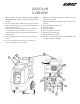
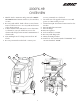
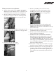
1. Handle- Used to maneuver and position the 2000CX-
HR/2000FX-HR. Contains switch box (for switchbox,
see #12).
2. Recovery tank and lid- Tank collects recovered waste
water. Lid allows access to recovery tank and creates a
seal to ensure suction.
3. Solution tank and lid- Tank used to store clean water
or solution for your job. Lid allows access to the
solution tank and prevents external contamination of
solution tank.
4. Non-marking front 4” locking casters and rear 10”
wheels.
5. Recovery/vacuum hose inlet barb- connect your
recovery vacuum hose to this barb.
6. Two male twist lock pigtails- Connect to two 50
power cord. One circuit per cord
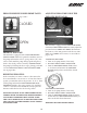
7. Solution line Q.D.- Pressurized connection for solu-
tion line.
8. Pressure Relief/ Power Prime
9. Pressure Gauge
10. Pressure regulator
11. Cool air intake for vacuum.
12. Recovery tank dump valve
13. Heater mounting brackets.
14. Switch box- Two switches marked “VACUUM” and
one switch marked “PUMP”.
3
2
1
4
6
8
9
5
12
14
10
13
7
11
2000FX-HR
OVERVIEW