GALAXY 2000CX-HR 2000FX-HR PROFESSIONAL 12 GALLON CARPET EXTRACTOR OWNER’S/OPERATOR’S MANUAL PROUDLY DESIGNED AND MANUFACTURED BY WWW.EDIC-USA.
TABLE OF CONTENTS RECEIVING YOUR EQUIPMENT................................................................................... 3 WARNINGS AND SAFETY.............................................................................................. 3, 4 ELECTRICAL INFORMATION....................................................................................... 4 GROUNDING INSTRUCTIONS...................................................................................... 4 MAINTENANCE...............................
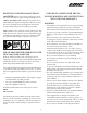
RECEIVING YOUR NEW 2000CX-HR OR 2000FX-HR: When your package is delivered, check the carton carefully for signs of rough handling. If your 2000CX-HR/2000FX-HR is damaged, notify the carrier immediately and request an inspection. Be sure to keep the carton, packing inserts, packing lists and carrier’s receipt until the inspector has verified your claim. EDIC’s liability ceases when the carrier picks up the shipment.
• • • • • • • • • • • • • • • All repairs must be done by an authorized EDIC repair station. Do not use replacement parts other than original EDIC parts. Do not allow your spray stream to remain in one fixed location as surface damage may occur. Check that all spray nozzles are securely fastened. Loose nozzles could be ejected from equipment at high speeds. This is not a toy. Keep away from children. Do not pull by the power or use power cord as a handle.
MAINTENANCE: This 2000CX-HR/2000FX-HR has been engineered and built to require minimum maintenance. But like any machine, it does require basic care to keep it in optimum working condition. Careful attention to these maintenance instructions will give you maximum operating performance and life expectancy of the machine.
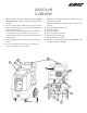
2000CX-HR OVERVIEW 1. Handle- Used to maneuver and position the 2000CXHR/2000FX-HR. Contains switch box (for switchbox, see #12). 2. Recovery tank and lid- Tank collects recovered waste water. Lid allows access to recovery tank and creates a seal to ensure suction. 3. Solution tank and lid- Tank used to store clean water or solution for your job. Lid allows access to the solution tank and prevents external contamination of solution tank. 4. Non-marking front 4” locking casters and rear 10” wheels. 5.
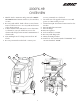
2000FX-HR OVERVIEW 1. Handle- Used to maneuver and position the 2000CXHR/2000FX-HR. Contains switch box (for switchbox, see #12). 2. Recovery tank and lid- Tank collects recovered waste water. Lid allows access to recovery tank and creates a seal to ensure suction. 3. Solution tank and lid- Tank used to store clean water or solution for your job. Lid allows access to the solution tank and prevents external contamination of solution tank. 4. Non-marking front 4” locking casters and rear 10” wheels. 5.
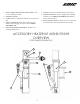
1. INLET QUICK DISCONNECT AND HOSE- Connects to machine’s outlet. 2. POWER SWITCH. 3. LAMP- Indicates when heat element is on and working. 4. TWIST LOCK PIG-TAIL- This connects to the female twistlock plug on the rear of the 2000CXHR/2000FX-HR. 5. OUTLET QUICK DISCONNECT- Connects to working solution line. 6. HANDLE- Used to hold and transport the heater 7. MOUNTING FEET- Used to engage the mounting brackets on an 2000CX-HR/2000FX-HR extractor and secure the heater. 8.
How to use an accessory heater: 1. Fill the solution tank of your 2000CX-HR/2000FXHR extractor with sufficient water or solution for the task at hand. Do not use water over 130 degrees F. 2. Mount the Heater by lining up the two mounting legs (See #7 on page 8) to the two mounting brackets on the rear of the machine (#11 on pages 6&7). 3. Connect your heater’s inlet hose (#1 on page 8) to the machine’s outlet quick disconnect (#7 on pages 6&7). 4. Connect your 25ft solution hose to the heater’s Q.D.
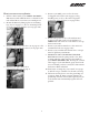
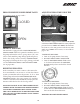
PRESSURE RELIEF/POWER PRIME VALVE: For location, see #8 on page 6 and 7. ADJUSTING PRESSURE USING THE PRESSURE REGULATOR: CLOSED Pressure gauge Pressure regulator OPEN PRIMING THE PUMP: This machine is equipped with a PRESSURE RELIEF/ POWER PRIME VALVE. To prime the machine, turn on the pump and turn the valve to open position (“O”) wait a few seconds until the pump changes pitch and place it back to the closed position.
CLEANING CARPET: 1. Using a dedicated dry vacuum, pre-vacuum the space to be cleaned to remove as much dirt as possible. Do not use the extractor to dry vacuum as it does not have a dry filter. 2. Pre-spray the carpet 3. See steps 1-11 in section “How to use an accessory heater” 4. Make sure the drain valve (#10 on page 6) is closed by pushing the T-handle all the way in. 5.
WIRING DIAGRAM 2000CX-HR 2700CX-HR 7-6-16 HANDLE MOTOR HOUSING BLACK WHITE 12
WIRING DIAGRAM 2000FX-HR 2700FX-HR 7-6-16 HANDLE MOTOR HOUSING BLACK BLACK WHITE PINK YELLOW AC AC BLACK RED RECTIFIER 2 WHITE 13
15 16 17 18 19 20 21 22 23 24 25 26 13 27 12 28 29 11 30 10 31 32 9 9D 9A 9B 8 9C 3 33 2 38 1 34 39 35 40 36 41 34 42 36 43 37 44 45 46 47 52 51 2000CX-HR UPPER 48 4 6 5 47 6-23-16 50 49 14 I
2000CX-HR UPPER 6-23-16 25 26 27 28 29 30 31 32 33 34 35 36 37 R ITEM NO. 1 2 3 4 5 6 8 9 9A 9B 9C 9D 10 11 12 13 14 15 16 17 18 19 20 21 22 23 24 25 26 27 28 29 30 31 32 33 34 35 36 37 38 39 40 41 42 43 44 45 46 47 48 49 50 51 52 PART NUMBER QTY. F11787 Solution Tank F11788 Recovery Tank F11791 Lid, Solution Tank A00060 3-8 Barb X 1-4MP, Brass A00052 90 Elbow, .25MP X .25FP C11244 Washer, .56 X 1.5 X .05 E11124 Gasket, Recovery Tank 12904A Stand Pipe Assembly K11965 Elbow, 180 Deg.
14 15 16 17 18 19 20 21 22 23 24 25 26 13 27 12 28 29 11 30 10 31 32 9 9D 9A 9B 8 9C 3 33 2 38 1 34 39 35 40 36 41 34 42 36 43 37 44 45 46 47 52 51 48 4 6 5 2000FX-HR Upper 6-23-16 47 50 49 16 I
2000FX-HR Upper 6-23-16 25 26 27 28 29 30 ITEM NO. 1 F11787 Solution Tank 2 F11788 Recovery Tank 3 F11791 Lid, Solution Tank DESCRIPTION 31 32 33 34 35 36 37 er 8 9 9A 9B 9C 9D 10 11 12 13 14 15 16 17 18 19 20 21 22 23 24 25 26 27 28 29 30 31 32 33 34 35 36 37 38 39 40 41 42 43 44 45 46 47 48 49 50 51 52 E11124 Gasket, Recovery Tank 12904A Stand Pipe Assembly K11965 Elbow, 180 Deg. Float Ball K00672 Pvc Pipe, 1.
1 2 3 5 2000CX-HR BASE 6-23-16 6 4 7 8 9 10 11 3 27 12 70 13 3 69 14 15 23 20 14 21 22 33 24 17 7 31 19 18 16 23 30 25 16 7 29 28 26 34 19 6 32 26 30 35 67 68 39 38 64 65 66 36 30 37 41 40 42 63 46 60 47 61 45 44 43 62 55 59 58 57 56 10 49 54 52 7 53 18 51 50 49 48
2000CX-HR 6-23-16 16 23 37 41 42 31 ITEM NO. 1 2 3 4 5 6 7 8 9 10 11 12 13 14 15 16 17 18 19 20 21 22 23 24 25 26 27 28 29 30 31 32 33 34 35 36 37 38 39 40 41 42 43 44 45 46 47 48 49 50 51 52 53 54 55 56 57 58 59 60 61 62 63 64 65 66 67 68 69 70 PART NUMBER J13152 Double grip hose Clamp J11863 Vac Exhaust hose, 2” diameter J00639 Screw Clamp, 1.63 - 2.43in. J00618 Hose , V ac base to waste tank F11178-BLK Intercooler, Galaxy, Black C00273 Locknut, 1-4 X 20, Nylon, SS C00233 Washer, Flat, .
1 2 3 5 2000FX-HR BASE 6-23-16 6 4 7 8 9 10 11 3 27 12 70 13 3 69 14 15 23 20 14 21 22 33 24 17 7 31 19 18 16 23 30 25 16 7 29 28 26 34 19 6 32 26 30 35 67 68 39 38 64 65 66 36 30 37 41 40 42 63 46 60 47 61 45 44 43 62 55 59 58 57 56 10 49 54 52 7 53 20 51 50 49 48
2000FX-HR 6-23-16 16 23 37 41 42 31 ITEM NO. 1 2 3 4 5 6 7 8 9 10 11 12 13 14 15 16 17 18 19 20 21 22 23 24 25 26 27 28 29 30 31 32 33 34 35 36 37 38 39 40 41 42 43 44 45 46 47 48 49 50 51 52 53 54 55 56 57 58 59 60 61 62 63 64 65 66 67 68 69 70 PART NUMBER J13152 Double grip hose Clamp J11863 Vac Exhaust hose, 2” diameter J00639 Screw Clamp, 1.63 - 2.43in. J00618 Hose , V ac base to waste tank F11178-BLK Intercooler, Galaxy, Black C00273 Locknut, 1-4 X 20, Nylon, SS C00233 Washer, Flat, .
TROUBLESHOOTING ELECTRICAL SYSTEM PROBLEM NO ELECTRICAL POWER POWER IS INTERMITTENT TO ONE OR ALL MOTORS 1. 2. 1. 2. 3. SOLUTION Defective power cord. House or building circuit breaker tripped Faulty electrical cable. Defective switches. Loose terminal or discolored terminal connections. VACUUM SYSTEM PROBLEM NO VACUUM SUCTION 1. 2. 3. 1. 2. 3. 4. 5. LOW VACUUM SUCTION SOLUTION Drain Valve open. Vacuum lid is not sealed against tank.
NOTES _________________ 23
Quality Above All Warranty Registration: To register your product warranty, visit our website at: www.edic-usa.
Quality Above All warranty repairs will only be warranted for the remainder of the original warranty and not from their installation date. Any parts or product replaced under this Limited Warranty will become the property of EDIC. EXCEPTIONS AND EXCLUSIONS FROM THE WARRANTY. This Limited Warranty only covers product issues caused by defects in material or workmanship during normal service.