
Installation Guide
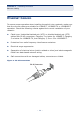
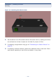
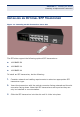
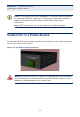
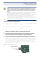
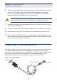

Table Of Contents
- Compliances and Safety Statements
- About This Guide
- Contents
- Tables
- Figures
- Introduction
- Network Planning
- Installing the Switch
- Making Network Connections
- Troubleshooting
- Cables
- Specifications
- Glossary
- Index

C
HAPTER
3
| Installing the Switch
Connecting to the Console Port
– 38 –
6. Insert the wire leads into the openings shown in the figure above. Each lead
inserted in the power plug must match the lead attached to the power
source. Use the labeling above the DC power connector to identify the
appropriate power input and return or ground lines.
7. Tighten down each wire clamp screw securely. You should not be able to pull
on a wire and dislodge it.
8. Insert the power plug into the power receptacle on the switch’s rear panel.
9. At the power source, turn on the power for the feed lines or power bus.
10. Check the Power LED indicator on the switch to verify that the power is on.
If not, recheck the power supply and power cable connections at the supply
source and at switch power connector.
CONNECTING TO THE CONSOLE PORT
This port is used to connect a console device to the switch through a serial cable.
The console device can be a PC or workstation running a VT-100 terminal
emulator, or a VT-100 terminal. A crossover RJ-45 to DB-9 cable is supplied with
the unit for connecting to the console port, as illustrated below. The PIN
assignments used to connect to the serial port are described below.
Figure 14: Console Cable
C
AUTION
:
If the power leads are plugged into the wrong holes, the
power supply will not work properly and may damage the switch.
RJ-45 Connector
Console Port
DB-9 Port
aaa
aaa
aaa
aaa
aaa
aaa