
Installation Guide
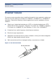
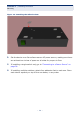
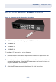
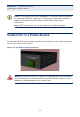
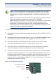
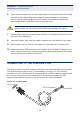

Table Of Contents
- Compliances and Safety Statements
- About This Guide
- Contents
- Tables
- Figures
- Introduction
- Network Planning
- Installing the Switch
- Making Network Connections
- Troubleshooting
- Cables
- Specifications
- Glossary
- Index

C
HAPTER
3
| Installing the Switch
Connecting to a Power Source
– 37 –
To connect the switch to a power source:
1. Verify that the external DC power supply can provide 36 to 75 VDC, 0.373 A
minimum.
2. Prepare two wires for the power source. Use 10 to 24 AWG stranded copper
wire. Make sure these wires are not plugged into the power source.
3. Use a wire stripper to carefully strip about a half an inch of the outer
insulation off the end of each wire, exposing the copper core.
4. Twist the copper wire strands together to form a tight braid. If possible,
solder the exposed braid of wire together for better conductivity.
5. Connect the external power feed and power ground/return lines to the DC
plug (provided with the switch). The power leads are labeled on the rear of
the switch, above the DC power connection block. The 48 VDC power feed
line connects to the “+” terminal, and the return line connects to the “-”
terminal. Use a small flat-tip screwdriver to loosen the screws on the power
plug and open the wire clamps.
Figure 13: DC Plug Connections
N
OTE
:
To provide adequate circuit protection between the DC power
supply and the switch, all intermediate wiring and circuitry should be
rated to carry a load at least two times the maximum rating for this
switch.
N
OTE
:
The wiring between the DC power supply and the switch must be
stranded copper wire within the range of 10 to 24 AWG.
N
OTE
:
Wiring for the power input terminals on the switch are described
below. Wiring of the DC power supply terminals depends on the
equipment in use on the local site. The wiring should also be color
coded according to local standards to ensure that the input power and
ground lines can be easily distinguished.
48 VDC power feed
Ground
DC power return