
Web Management Guide-R02
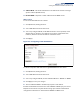
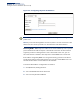
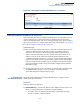
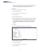
Table Of Contents
- How to Use This Guide
- Contents
- Figures
- Tables
- Getting Started
- Web Configuration
- Using the Web Interface
- Basic Management Tasks
- Displaying System Information
- Displaying Hardware/Software Versions
- Configuring Support for Jumbo Frames
- Displaying Bridge Extension Capabilities
- Managing System Files
- Setting the System Clock
- Configuring the Console Port
- Configuring Telnet Settings
- Displaying CPU Utilization
- Configuring CPU Guard
- Displaying Memory Utilization
- Resetting the System
- Interface Configuration
- VLAN Configuration
- Address Table Settings
- Spanning Tree Algorithm
- Congestion Control
- Class of Service
- Quality of Service
- VoIP Traffic Configuration
- Security Measures
- AAA (Authentication, Authorization and Accounting)
- Configuring User Accounts
- Web Authentication
- Network Access (MAC Address Authentication)
- Configuring HTTPS
- Configuring the Secure Shell
- Access Control Lists
- Filtering IP Addresses for Management Access
- Configuring Port Security
- Configuring 802.1X Port Authentication
- DoS Protection
- DHCP Snooping
- DHCPv6 Snooping
- ND Snooping
- IPv4 Source Guard
- IPv6 Source Guard
- ARP Inspection
- Application Filter
- Basic Administration Protocols
- Configuring Event Logging
- Link Layer Discovery Protocol
- Simple Network Management Protocol
- Configuring Global Settings for SNMP
- Setting Community Access Strings
- Setting the Local Engine ID
- Specifying a Remote Engine ID
- Setting SNMPv3 Views
- Configuring SNMPv3 Groups
- Configuring Local SNMPv3 Users
- Configuring Remote SNMPv3 Users
- Specifying Trap Managers
- Creating SNMP Notification Logs
- Showing SNMP Statistics
- Remote Monitoring
- Setting a Time Range
- Ethernet Ring Protection Switching
- MLAG Configuration
- OAM Configuration
- LBD Configuration
- Multicast Filtering
- Overview
- Layer 2 IGMP (Snooping and Query for IPv4)
- Configuring IGMP Snooping and Query Parameters
- Specifying Static Interfaces for a Multicast Router
- Assigning Interfaces to Multicast Services
- Setting IGMP Snooping Status per Interface
- Filtering IGMP Packets on an Interface
- Displaying Multicast Groups Discovered by IGMP Snooping
- Displaying IGMP Snooping Statistics
- Filtering and Throttling IGMP Groups
- MLD Snooping (Snooping and Query for IPv6)
- Configuring MLD Snooping and Query Parameters
- Setting Immediate Leave Status for MLD Snooping per Interface
- Specifying Static Interfaces for an IPv6 Multicast Router
- Assigning Interfaces to IPv6 Multicast Services
- Filtering MLD Query Packets on an Interface
- Showing MLD Snooping Groups and Source List
- Displaying MLD Snooping Statistics
- Filtering and Throttling MLD Groups
- Multicast VLAN Registration for IPv4
- IP Tools
- IP Configuration
- General IP Routing
- IP Services
- Appendices

– 601 –
16 IP Configuration
This chapter describes how to configure an IP interface for management access to
the switch over the network. This switch supports both IP Version 4 and Version 6,
and can be managed simultaneously through either of these address types. You
can manually configure a specific IPv4 or IPv6 address, or direct the switch to obtain
an IPv4 address from a BOOTP or DHCP server. An IPv6 address can either be
manually configured or dynamically generated.
This chapter provides information on network functions including:
◆ IPv4 Configuration – Sets an IPv4 address for management access.
◆ IPv6 Configuration – Sets an IPv6 address for management access.
Setting the Switch’s IP Address (IP Version 4)
This section describes how to configure an initial IPv4 interface for management
access over the network, and how to create an interface to multiple subnets. This
switch supports both IPv4 and IPv6, and can be managed through either of these
address types. You can manually configure a specific IPv4 or IPv6 address or direct
the switch to obtain an IPv4 address from a BOOTP or DHCP server. An IPv6 global
unicast or link-local address can be manually configured, or a link-local address can
be dynamically generated. For information on configuring the switch with an IPv6
address, see “Setting the Switch’s IP Address (IP Version 6)” on page 605.
Configuring IPv4
Interface Settings
Use the IP > General > Routing Interface (Add Address) page to configure an IPv4
address for the switch. An IPv4 address is obtained via DHCP by default for VLAN 1.
To configure a static address, you need to change the switch’s default settings to
values that are compatible with your network. You may also need to a establish a
default gateway between the switch and management stations that exist on
another network segment. To configure this device as the default gateway, use the
IP > Routing > Static Routes (Add) page, set the destination address to the required
interface, and the next hop to null address 0.0.0.0.
You can direct the device to obtain an address from a BOOTP or DHCP server, or
manually configure a static IP address. Valid IP addresses consist of four decimal
numbers, 0 to 255, separated by periods. Anything other than this format will not
be accepted.