
Web Management Guide-R02
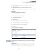
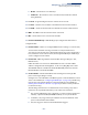
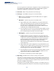
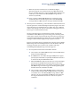
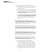
Table Of Contents
- How to Use This Guide
- Contents
- Figures
- Tables
- Getting Started
- Web Configuration
- Using the Web Interface
- Basic Management Tasks
- Displaying System Information
- Displaying Hardware/Software Versions
- Configuring Support for Jumbo Frames
- Displaying Bridge Extension Capabilities
- Managing System Files
- Setting the System Clock
- Configuring the Console Port
- Configuring Telnet Settings
- Displaying CPU Utilization
- Configuring CPU Guard
- Displaying Memory Utilization
- Resetting the System
- Interface Configuration
- VLAN Configuration
- Address Table Settings
- Spanning Tree Algorithm
- Congestion Control
- Class of Service
- Quality of Service
- VoIP Traffic Configuration
- Security Measures
- AAA (Authentication, Authorization and Accounting)
- Configuring User Accounts
- Web Authentication
- Network Access (MAC Address Authentication)
- Configuring HTTPS
- Configuring the Secure Shell
- Access Control Lists
- Filtering IP Addresses for Management Access
- Configuring Port Security
- Configuring 802.1X Port Authentication
- DoS Protection
- DHCP Snooping
- DHCPv6 Snooping
- ND Snooping
- IPv4 Source Guard
- IPv6 Source Guard
- ARP Inspection
- Application Filter
- Basic Administration Protocols
- Configuring Event Logging
- Link Layer Discovery Protocol
- Simple Network Management Protocol
- Configuring Global Settings for SNMP
- Setting Community Access Strings
- Setting the Local Engine ID
- Specifying a Remote Engine ID
- Setting SNMPv3 Views
- Configuring SNMPv3 Groups
- Configuring Local SNMPv3 Users
- Configuring Remote SNMPv3 Users
- Specifying Trap Managers
- Creating SNMP Notification Logs
- Showing SNMP Statistics
- Remote Monitoring
- Setting a Time Range
- Ethernet Ring Protection Switching
- MLAG Configuration
- OAM Configuration
- LBD Configuration
- Multicast Filtering
- Overview
- Layer 2 IGMP (Snooping and Query for IPv4)
- Configuring IGMP Snooping and Query Parameters
- Specifying Static Interfaces for a Multicast Router
- Assigning Interfaces to Multicast Services
- Setting IGMP Snooping Status per Interface
- Filtering IGMP Packets on an Interface
- Displaying Multicast Groups Discovered by IGMP Snooping
- Displaying IGMP Snooping Statistics
- Filtering and Throttling IGMP Groups
- MLD Snooping (Snooping and Query for IPv6)
- Configuring MLD Snooping and Query Parameters
- Setting Immediate Leave Status for MLD Snooping per Interface
- Specifying Static Interfaces for an IPv6 Multicast Router
- Assigning Interfaces to IPv6 Multicast Services
- Filtering MLD Query Packets on an Interface
- Showing MLD Snooping Groups and Source List
- Displaying MLD Snooping Statistics
- Filtering and Throttling MLD Groups
- Multicast VLAN Registration for IPv4
- IP Tools
- IP Configuration
- General IP Routing
- IP Services
- Appendices

Chapter 13
| Basic Administration Protocols
Ethernet Ring Protection Switching
– 482 –
Figure 314: Configuring ERPS VLAN Groups
ERPS Ring
Configuration
Use the Administration > ERPS (Configure Ring) pages to configure a physical ERPS
ring.
Command Usage
◆ The switch can support ERPS rings up to half the number of physical ports on
the switch.
◆ Each node must be connected to two neighbors on the ring. For convenience,
the ports connected are referred to as east and west ports. Alternatively, the
closest neighbor to the east should be the next node in the ring in a clockwise
direction, and the closest neighbor to the west should be the next node in the
ring in a counter-clockwise direction.
◆ Note that a ring port cannot be configured as a member of a spanning tree, a
dynamic trunk, or a static trunk.
◆ If a port channel (static trunk) is specified as a ring port, it can not be destroyed
before it is removed from the ring configuration. A static trunk will be treated as
a signal fault, if it contains no member ports or all of its member ports are in
signal fault. If a static trunk is configured as a ring port prior to assigning any
member ports, spanning tree will be disabled for the first member port
assigned to the static trunk.
◆ VLANs that are on the exclusion list are not protected by the ERPS ring. Any
VLAN not listed on either the inclusion or exclusion list will be blocked on ring
ports.
◆ Traffic from control VLANs, inclusion VLANs, and exclusion VLANs of an ERPS
ring will be forwarded by non-ERPS ring ports.
Parameters
These parameters are displayed:
◆ Ring Name – Name of the VLAN group. (Range: 1-12 characters).
◆ West – The port that connects to the next ring node to the west.
◆ East – The port that connects to the next ring node to the east.