
Web Management Guide-R02
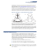
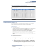

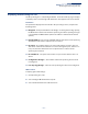
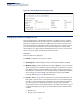
Table Of Contents
- How to Use This Guide
- Contents
- Figures
- Tables
- Getting Started
- Web Configuration
- Using the Web Interface
- Basic Management Tasks
- Displaying System Information
- Displaying Hardware/Software Versions
- Configuring Support for Jumbo Frames
- Displaying Bridge Extension Capabilities
- Managing System Files
- Setting the System Clock
- Configuring the Console Port
- Configuring Telnet Settings
- Displaying CPU Utilization
- Configuring CPU Guard
- Displaying Memory Utilization
- Resetting the System
- Interface Configuration
- VLAN Configuration
- Address Table Settings
- Spanning Tree Algorithm
- Congestion Control
- Class of Service
- Quality of Service
- VoIP Traffic Configuration
- Security Measures
- AAA (Authentication, Authorization and Accounting)
- Configuring User Accounts
- Web Authentication
- Network Access (MAC Address Authentication)
- Configuring HTTPS
- Configuring the Secure Shell
- Access Control Lists
- Filtering IP Addresses for Management Access
- Configuring Port Security
- Configuring 802.1X Port Authentication
- DoS Protection
- DHCP Snooping
- DHCPv6 Snooping
- ND Snooping
- IPv4 Source Guard
- IPv6 Source Guard
- ARP Inspection
- Application Filter
- Basic Administration Protocols
- Configuring Event Logging
- Link Layer Discovery Protocol
- Simple Network Management Protocol
- Configuring Global Settings for SNMP
- Setting Community Access Strings
- Setting the Local Engine ID
- Specifying a Remote Engine ID
- Setting SNMPv3 Views
- Configuring SNMPv3 Groups
- Configuring Local SNMPv3 Users
- Configuring Remote SNMPv3 Users
- Specifying Trap Managers
- Creating SNMP Notification Logs
- Showing SNMP Statistics
- Remote Monitoring
- Setting a Time Range
- Ethernet Ring Protection Switching
- MLAG Configuration
- OAM Configuration
- LBD Configuration
- Multicast Filtering
- Overview
- Layer 2 IGMP (Snooping and Query for IPv4)
- Configuring IGMP Snooping and Query Parameters
- Specifying Static Interfaces for a Multicast Router
- Assigning Interfaces to Multicast Services
- Setting IGMP Snooping Status per Interface
- Filtering IGMP Packets on an Interface
- Displaying Multicast Groups Discovered by IGMP Snooping
- Displaying IGMP Snooping Statistics
- Filtering and Throttling IGMP Groups
- MLD Snooping (Snooping and Query for IPv6)
- Configuring MLD Snooping and Query Parameters
- Setting Immediate Leave Status for MLD Snooping per Interface
- Specifying Static Interfaces for an IPv6 Multicast Router
- Assigning Interfaces to IPv6 Multicast Services
- Filtering MLD Query Packets on an Interface
- Showing MLD Snooping Groups and Source List
- Displaying MLD Snooping Statistics
- Filtering and Throttling MLD Groups
- Multicast VLAN Registration for IPv4
- IP Tools
- IP Configuration
- General IP Routing
- IP Services
- Appendices

Chapter 7
| Spanning Tree Algorithm
Configuring Loopback Detection
– 211 –
An MST Region consists of a group of interconnected bridges that have the same
MST Configuration Identifiers (including the Region Name, Revision Level and
Configuration Digest – see “Configuring Multiple Spanning Trees” on page 227). An
MST Region may contain multiple MSTP Instances. An Internal Spanning Tree (IST)
is used to connect all the MSTP switches within an MST region. A Common
Spanning Tree (CST) interconnects all adjacent MST Regions, and acts as a virtual
bridge node for communications with STP or RSTP nodes in the global network.
Figure 122: Spanning Tree – Common Internal, Common, Internal
MSTP connects all bridges and LAN segments with a single Common and Internal
Spanning Tree (CIST). The CIST is formed as a result of the running spanning tree
algorithm between switches that support the STP, RSTP, MSTP protocols.
Once you specify the VLANs to include in a Multiple Spanning Tree Instance (MSTI),
the protocol will automatically build an MSTI tree to maintain connectivity among
each of the VLANs. MSTP maintains contact with the global network because each
instance is treated as an RSTP node in the Common Spanning Tree (CST).
Configuring Loopback Detection
Use the Spanning Tree > Loopback Detection page to configure loopback
detection on an interface. When loopback detection is enabled and a port or trunk
receives it’s own BPDU, the detection agent drops the loopback BPDU, sends an
SNMP trap, and places the interface in discarding mode. This loopback state can be
released manually or automatically. If the interface is configured for automatic
loopback release, then the port will only be returned to the forwarding state if one
of the following conditions is satisfied:
◆ The interface receives any other BPDU except for it’s own, or;
◆ The interface link status changes to link down and then link up again, or;
◆ The interface ceases to receive it’s own BPDUs in a forward delay interval.
Note:
If loopback detection is not enabled and an interface receives it's own BPDU,
then the interface will drop the loopback BPDU according to IEEE Standard 802.1w-
2001 9.3.4 (Note 1).
Region 1
Region 4
Region 2 Region 3
CIST
IST
Region 1
Region 4
Region 2 Region 3
CST