
Web Management Guide-R02
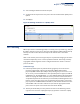
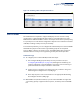
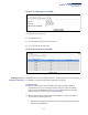
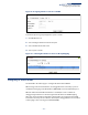
Table Of Contents
- How to Use This Guide
- Contents
- Figures
- Tables
- Getting Started
- Web Configuration
- Using the Web Interface
- Basic Management Tasks
- Displaying System Information
- Displaying Hardware/Software Versions
- Configuring Support for Jumbo Frames
- Displaying Bridge Extension Capabilities
- Managing System Files
- Setting the System Clock
- Configuring the Console Port
- Configuring Telnet Settings
- Displaying CPU Utilization
- Configuring CPU Guard
- Displaying Memory Utilization
- Resetting the System
- Interface Configuration
- VLAN Configuration
- Address Table Settings
- Spanning Tree Algorithm
- Congestion Control
- Class of Service
- Quality of Service
- VoIP Traffic Configuration
- Security Measures
- AAA (Authentication, Authorization and Accounting)
- Configuring User Accounts
- Web Authentication
- Network Access (MAC Address Authentication)
- Configuring HTTPS
- Configuring the Secure Shell
- Access Control Lists
- Filtering IP Addresses for Management Access
- Configuring Port Security
- Configuring 802.1X Port Authentication
- DoS Protection
- DHCP Snooping
- DHCPv6 Snooping
- ND Snooping
- IPv4 Source Guard
- IPv6 Source Guard
- ARP Inspection
- Application Filter
- Basic Administration Protocols
- Configuring Event Logging
- Link Layer Discovery Protocol
- Simple Network Management Protocol
- Configuring Global Settings for SNMP
- Setting Community Access Strings
- Setting the Local Engine ID
- Specifying a Remote Engine ID
- Setting SNMPv3 Views
- Configuring SNMPv3 Groups
- Configuring Local SNMPv3 Users
- Configuring Remote SNMPv3 Users
- Specifying Trap Managers
- Creating SNMP Notification Logs
- Showing SNMP Statistics
- Remote Monitoring
- Setting a Time Range
- Ethernet Ring Protection Switching
- MLAG Configuration
- OAM Configuration
- LBD Configuration
- Multicast Filtering
- Overview
- Layer 2 IGMP (Snooping and Query for IPv4)
- Configuring IGMP Snooping and Query Parameters
- Specifying Static Interfaces for a Multicast Router
- Assigning Interfaces to Multicast Services
- Setting IGMP Snooping Status per Interface
- Filtering IGMP Packets on an Interface
- Displaying Multicast Groups Discovered by IGMP Snooping
- Displaying IGMP Snooping Statistics
- Filtering and Throttling IGMP Groups
- MLD Snooping (Snooping and Query for IPv6)
- Configuring MLD Snooping and Query Parameters
- Setting Immediate Leave Status for MLD Snooping per Interface
- Specifying Static Interfaces for an IPv6 Multicast Router
- Assigning Interfaces to IPv6 Multicast Services
- Filtering MLD Query Packets on an Interface
- Showing MLD Snooping Groups and Source List
- Displaying MLD Snooping Statistics
- Filtering and Throttling MLD Groups
- Multicast VLAN Registration for IPv4
- IP Tools
- IP Configuration
- General IP Routing
- IP Services
- Appendices

Chapter 5
| VLAN Configuration
L2PT Tunneling
– 181 –
2. Select Configure Interface from the Step list.
3. Set the mode for any tunnel access port to Access and the tunnel uplink port to
Uplink.
4. Click Apply.
Figure 94: Adding an Interface to a QinQ Tunnel
L2PT Tunneling
When Layer 2 Protocol Tunneling (L2PT) is not used, protocol packets (e.g., STP) are
flooded to 802.1Q access ports on the same edge switch, but filtered from 802.1Q
tunnel ports. This creates disconnected protocol domains in the customer’s
network.
L2PT can be used to pass various types of protocol packets belonging to the same
customer transparently across a service provider’s network. In this way, normally
segregated network segments can be configured to function inside a common
protocol domain.
Command Usage
◆ L2PT encapsulates protocol packets entering ingress ports on the service
provider’s edge switch, replacing the destination MAC address with a
proprietary MAC address (for example, the spanning tree protocol uses 10-12-
CF-00-00-02), a reserved address for other specified protocol types (as defined
in IEEE 802.1ad – Provider Bridges), or a user-defined address. All intermediate
switches carrying this traffic across the service provider’s network treat these
encapsulated packets in the same way as normal data, forwarding them to the
tunnel’s egress port. The egress port decapsulates these packets, restores the
proper protocol and MAC address information, and then floods them onto the
same VLANs at the customer’s remote site (via all of the appropriate tunnel
ports and access ports
4
connected to the same metro VLAN).
◆ The way in which L2PT processes packets is based on the following criteria –
(1) packet is received on a QinQ uplink port, (2) packet is received on a QinQ
4. Access ports in this context are 802.1Q trunk ports.