
Web Management Guide-R05


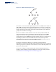


Table Of Contents
- ECS4810-12M Gigabit Ethernet Switch
- How to Use This Guide
- Contents
- Figures
- Tables
- Getting Started
- Web Configuration
- Using the Web Interface
- Basic Management Tasks
- Displaying System Information
- Displaying Hardware/Software Versions
- Configuring Support for Jumbo Frames
- Displaying Bridge Extension Capabilities
- Managing System Files
- Setting the System Clock
- Configuring the Console Port
- Configuring Telnet Settings
- Displaying CPU Utilization
- Displaying Memory Utilization
- Resetting the System
- Interface Configuration
- VLAN Configuration
- Address Table Settings
- Spanning Tree Algorithm
- Congestion Control
- Class of Service
- Quality of Service
- VoIP Traffic Configuration
- Security Measures
- AAA (Authentication, Authorization and Accounting)
- Configuring User Accounts
- Web Authentication
- Network Access (MAC Address Authentication)
- Configuring HTTPS
- Configuring the Secure Shell
- Access Control Lists
- Setting a Time Range
- Showing TCAM Utilization
- Setting the ACL Name and Type
- Configuring a Standard IPv4 ACL
- Configuring an Extended IPv4 ACL
- Configuring a Standard IPv6 ACL
- Configuring an Extended IPv6 ACL
- Configuring a MAC ACL
- Configuring an ARP ACL
- Binding a Port to an Access Control List
- Configuring ACL Mirroring
- Showing ACL Hardware Counters
- ARP Inspection
- Filtering IP Addresses for Management Access
- Configuring Port Security
- Configuring 802.1X Port Authentication
- DoS Protection
- IP Source Guard
- DHCP Snooping
- Basic Administration Protocols
- Configuring Event Logging
- Link Layer Discovery Protocol
- Simple Network Management Protocol
- Configuring Global Settings for SNMP
- Setting the Local Engine ID
- Specifying a Remote Engine ID
- Setting SNMPv3 Views
- Configuring SNMPv3 Groups
- Setting Community Access Strings
- Configuring Local SNMPv3 Users
- Configuring Remote SNMPv3 Users
- Specifying Trap Managers
- Creating SNMP Notification Logs
- Showing SNMP Statistics
- Remote Monitoring
- Switch Clustering
- Ethernet Ring Protection Switching
- Connectivity Fault Management
- Configuring Global Settings for CFM
- Configuring Interfaces for CFM
- Configuring CFM Maintenance Domains
- Configuring CFM Maintenance Associations
- Configuring Maintenance End Points
- Configuring Remote Maintenance End Points
- Transmitting Link Trace Messages
- Transmitting Loop Back Messages
- Transmitting Delay-Measure Requests
- Displaying Local MEPs
- Displaying Details for Local MEPs
- Displaying Local MIPs
- Displaying Remote MEPs
- Displaying Details for Remote MEPs
- Displaying the Link Trace Cache
- Displaying Fault Notification Settings
- Displaying Continuity Check Errors
- OAM Configuration
- UDLD Configuration
- IP Configuration
- IP Services
- Multicast Filtering
- Overview
- Layer 2 IGMP (Snooping and Query for IPv4)
- Configuring IGMP Snooping and Query Parameters
- Specifying Static Interfaces for a Multicast Router
- Assigning Interfaces to Multicast Services
- Setting IGMP Snooping Status per Interface
- Filtering IGMP Query and Report Packets
- Displaying Multicast Groups Discovered by IGMP Snooping
- Displaying IGMP Snooping Statistics
- Filtering and Throttling IGMP Groups
- MLD Snooping (Snooping and Query for IPv6)
- Multicast VLAN Registration for IPv4
- Multicast VLAN Registration for IPv6
- Appendices
- Glossary
- Index

Chapter 15
| IP Services
Configuring the PPPoE Intermediate Agent
– 564 –
◆
PPPoE IA Status
– Enables the PPPoE IA on an interface. (Default: Disabled)
Note that PPPoE IA must also be enabled globally on the switch for this
command to take effect.
◆
Trust Status
– Sets an interface to trusted mode to indicate that it is connected
to a PPPoE server. (Default: Disabled)
■
Set any interfaces connecting the switch to a PPPoE Server as trusted.
Interfaces that connect the switch to users (PPPoE clients) should be set as
untrusted.
■
At least one trusted interface must be configured on the switch for the
PPPoE IA to function.
◆
Vendor Tag Strip
– Enables the stripping of vendor tags from PPPoE Discovery
packets sent from a PPPoE server. (Default: Disabled)
This parameter only applies to trusted interfaces. It is used to strip off vendor-
specific tags (which carry subscriber and line identification information) in
PPPoE Discovery packets received from an upstream PPPoE server before
forwarding them to a user.
◆
Circuit ID
– String identifying the circuit identifier (or interface) on this switch
to which the user is connected. (Range: 1-10 ASCII characters; Default: Unit/
Port:VLAN-ID, or 0/Trunk-ID:VLAN-ID)
■
The PPPoE server extracts the Line-ID tag from PPPoE discovery stage
messages, and uses the Circuit-ID field of that tag as a NAS-Port-ID attribute
in AAA access and accounting requests.
■
The switch intercepts PPPoE discovery frames from the client and inserts a
unique line identifier using the PPPoE Vendor-Specific tag (0x0105) to
PPPoE Active Discovery Initiation (PADI) and Request (PADR) packets. The
switch then forwards these packets to the PPPoE server. The tag contains
the Line-ID of the customer line over which the discovery packet was
received, entering the switch (or access node) where the intermediate
agent resides.
■
Outgoing PAD Offer (PADO) and Session-confirmation (PADS) packets sent
from the PPPoE Server include the Circuit-ID tag inserted by the switch, and
should be stripped out of PADO and PADS packets which are to be passed
directly to end-node clients.
◆
Operational Circuit ID
– The configured circuit identifier.
◆
Remote ID
– String identifying the remote identifier (or interface) on this
switch to which the user is connected. (Range: 1-63 ASCII characters;
Default: Port MAC address)
◆
Operational Remote ID
– The configured circuit identifier.