
Web Management Guide-R05
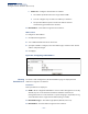
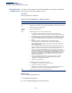
Table Of Contents
- ECS4810-12M Gigabit Ethernet Switch
- How to Use This Guide
- Contents
- Figures
- Tables
- Getting Started
- Web Configuration
- Using the Web Interface
- Basic Management Tasks
- Displaying System Information
- Displaying Hardware/Software Versions
- Configuring Support for Jumbo Frames
- Displaying Bridge Extension Capabilities
- Managing System Files
- Setting the System Clock
- Configuring the Console Port
- Configuring Telnet Settings
- Displaying CPU Utilization
- Displaying Memory Utilization
- Resetting the System
- Interface Configuration
- VLAN Configuration
- Address Table Settings
- Spanning Tree Algorithm
- Congestion Control
- Class of Service
- Quality of Service
- VoIP Traffic Configuration
- Security Measures
- AAA (Authentication, Authorization and Accounting)
- Configuring User Accounts
- Web Authentication
- Network Access (MAC Address Authentication)
- Configuring HTTPS
- Configuring the Secure Shell
- Access Control Lists
- Setting a Time Range
- Showing TCAM Utilization
- Setting the ACL Name and Type
- Configuring a Standard IPv4 ACL
- Configuring an Extended IPv4 ACL
- Configuring a Standard IPv6 ACL
- Configuring an Extended IPv6 ACL
- Configuring a MAC ACL
- Configuring an ARP ACL
- Binding a Port to an Access Control List
- Configuring ACL Mirroring
- Showing ACL Hardware Counters
- ARP Inspection
- Filtering IP Addresses for Management Access
- Configuring Port Security
- Configuring 802.1X Port Authentication
- DoS Protection
- IP Source Guard
- DHCP Snooping
- Basic Administration Protocols
- Configuring Event Logging
- Link Layer Discovery Protocol
- Simple Network Management Protocol
- Configuring Global Settings for SNMP
- Setting the Local Engine ID
- Specifying a Remote Engine ID
- Setting SNMPv3 Views
- Configuring SNMPv3 Groups
- Setting Community Access Strings
- Configuring Local SNMPv3 Users
- Configuring Remote SNMPv3 Users
- Specifying Trap Managers
- Creating SNMP Notification Logs
- Showing SNMP Statistics
- Remote Monitoring
- Switch Clustering
- Ethernet Ring Protection Switching
- Connectivity Fault Management
- Configuring Global Settings for CFM
- Configuring Interfaces for CFM
- Configuring CFM Maintenance Domains
- Configuring CFM Maintenance Associations
- Configuring Maintenance End Points
- Configuring Remote Maintenance End Points
- Transmitting Link Trace Messages
- Transmitting Loop Back Messages
- Transmitting Delay-Measure Requests
- Displaying Local MEPs
- Displaying Details for Local MEPs
- Displaying Local MIPs
- Displaying Remote MEPs
- Displaying Details for Remote MEPs
- Displaying the Link Trace Cache
- Displaying Fault Notification Settings
- Displaying Continuity Check Errors
- OAM Configuration
- UDLD Configuration
- IP Configuration
- IP Services
- Multicast Filtering
- Overview
- Layer 2 IGMP (Snooping and Query for IPv4)
- Configuring IGMP Snooping and Query Parameters
- Specifying Static Interfaces for a Multicast Router
- Assigning Interfaces to Multicast Services
- Setting IGMP Snooping Status per Interface
- Filtering IGMP Query and Report Packets
- Displaying Multicast Groups Discovered by IGMP Snooping
- Displaying IGMP Snooping Statistics
- Filtering and Throttling IGMP Groups
- MLD Snooping (Snooping and Query for IPv6)
- Multicast VLAN Registration for IPv4
- Multicast VLAN Registration for IPv6
- Appendices
- Glossary
- Index

Chapter 14
| IP Configuration
Setting the Switch’s IP Address (IP Version 6)
– 532 –
using the modified EUI-64 form of the interface identifier (i.e., the switch’s MAC
address).
■
If a link local address has not yet been assigned to this interface, this
command will dynamically generate one. The link-local address is made
with an address prefix in the range of FE80~FEBF and a host portion based
the switch’s MAC address in modified EUI-64 format. It will also generate a
global unicast address if a global prefix is included in received router
advertisements.
■
When DHCPv6 is started, the switch may attempt to acquire an IP address
prefix through stateful address autoconfiguration. If router advertisements
have the “other stateful configuration” flag set, the switch will attempt to
acquire other non-address configuration information (such as a default
gateway).
■
If auto-configuration is not selected, then an address must be manually
configured using the Add IPv6 Address page described below.
◆
Enable IPv6 Explicitly
– Enables IPv6 on an interface and assigns it a link-local
address. Note that when an explicit address is assigned to an interface, IPv6 is
automatically enabled, and cannot be disabled until all assigned addresses
have been removed. (Default: Disabled)
Disabling this parameter does not disable IPv6 for an interface that has been
explicitly configured with an IPv6 address.
◆
MTU
– Sets the size of the maximum transmission unit (MTU) for IPv6 packets
sent on an interface. (Range: 1280-65535 bytes; Default: 1500 bytes)
■
The maximum value set in this field cannot exceed the MTU of the physical
interface, which is currently fixed at 1500 bytes.
■
If a non-default value is configured, an MTU option is included in the router
advertisements sent from this device. This option is provided to ensure that
all nodes on a link use the same MTU value in cases where the link MTU is
not otherwise well known.IPv6 routers do not fragment IPv6 packets
forwarded from other routers. However, traffic originating from an end-
station connected to an IPv6 router may be fragmented.
■
All devices on the same physical medium must use the same MTU in order
to operate correctly.
■
IPv6 must be enabled on an interface before the MTU can be set. If an IPv6
address has not been assigned to the switch, “N/A” is displayed in the MTU
field.
◆
ND DAD Attempts
– The number of consecutive neighbor solicitation
messages sent on an interface during duplicate address detection.
(Range: 0-600, Default: 3)
■
Configuring a value of 0 disables duplicate address detection.
■
Duplicate address detection determines if a new unicast IPv6 address
already exists on the network before it is assigned to an interface.