
Web Management Guide-R05
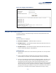
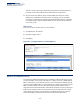
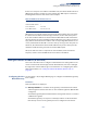
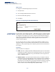
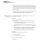
Table Of Contents
- ECS4810-12M Gigabit Ethernet Switch
- How to Use This Guide
- Contents
- Figures
- Tables
- Getting Started
- Web Configuration
- Using the Web Interface
- Basic Management Tasks
- Displaying System Information
- Displaying Hardware/Software Versions
- Configuring Support for Jumbo Frames
- Displaying Bridge Extension Capabilities
- Managing System Files
- Setting the System Clock
- Configuring the Console Port
- Configuring Telnet Settings
- Displaying CPU Utilization
- Displaying Memory Utilization
- Resetting the System
- Interface Configuration
- VLAN Configuration
- Address Table Settings
- Spanning Tree Algorithm
- Congestion Control
- Class of Service
- Quality of Service
- VoIP Traffic Configuration
- Security Measures
- AAA (Authentication, Authorization and Accounting)
- Configuring User Accounts
- Web Authentication
- Network Access (MAC Address Authentication)
- Configuring HTTPS
- Configuring the Secure Shell
- Access Control Lists
- Setting a Time Range
- Showing TCAM Utilization
- Setting the ACL Name and Type
- Configuring a Standard IPv4 ACL
- Configuring an Extended IPv4 ACL
- Configuring a Standard IPv6 ACL
- Configuring an Extended IPv6 ACL
- Configuring a MAC ACL
- Configuring an ARP ACL
- Binding a Port to an Access Control List
- Configuring ACL Mirroring
- Showing ACL Hardware Counters
- ARP Inspection
- Filtering IP Addresses for Management Access
- Configuring Port Security
- Configuring 802.1X Port Authentication
- DoS Protection
- IP Source Guard
- DHCP Snooping
- Basic Administration Protocols
- Configuring Event Logging
- Link Layer Discovery Protocol
- Simple Network Management Protocol
- Configuring Global Settings for SNMP
- Setting the Local Engine ID
- Specifying a Remote Engine ID
- Setting SNMPv3 Views
- Configuring SNMPv3 Groups
- Setting Community Access Strings
- Configuring Local SNMPv3 Users
- Configuring Remote SNMPv3 Users
- Specifying Trap Managers
- Creating SNMP Notification Logs
- Showing SNMP Statistics
- Remote Monitoring
- Switch Clustering
- Ethernet Ring Protection Switching
- Connectivity Fault Management
- Configuring Global Settings for CFM
- Configuring Interfaces for CFM
- Configuring CFM Maintenance Domains
- Configuring CFM Maintenance Associations
- Configuring Maintenance End Points
- Configuring Remote Maintenance End Points
- Transmitting Link Trace Messages
- Transmitting Loop Back Messages
- Transmitting Delay-Measure Requests
- Displaying Local MEPs
- Displaying Details for Local MEPs
- Displaying Local MIPs
- Displaying Remote MEPs
- Displaying Details for Remote MEPs
- Displaying the Link Trace Cache
- Displaying Fault Notification Settings
- Displaying Continuity Check Errors
- OAM Configuration
- UDLD Configuration
- IP Configuration
- IP Services
- Multicast Filtering
- Overview
- Layer 2 IGMP (Snooping and Query for IPv4)
- Configuring IGMP Snooping and Query Parameters
- Specifying Static Interfaces for a Multicast Router
- Assigning Interfaces to Multicast Services
- Setting IGMP Snooping Status per Interface
- Filtering IGMP Query and Report Packets
- Displaying Multicast Groups Discovered by IGMP Snooping
- Displaying IGMP Snooping Statistics
- Filtering and Throttling IGMP Groups
- MLD Snooping (Snooping and Query for IPv6)
- Multicast VLAN Registration for IPv4
- Multicast VLAN Registration for IPv6
- Appendices
- Glossary
- Index

Chapter 14
| IP Configuration
Setting the Switch’s IP Address (IP Version 4)
– 525 –
If there is no entry for an IP address in the ARP cache, the switch will broadcast an
ARP request packet to all devices on the network. The ARP request contains the
following fields similar to that shown in this example:
When devices receive this request, they discard it if their address does not match
the destination IP address in the message. However, if it does match, they write
their own hardware address into the destination MAC address field and send the
message back to the source hardware address. When the source device receives a
reply, it writes the destination IP address and corresponding MAC address into its
cache, and forwards the IP traffic on to the next hop. As long as this entry has not
timed out, the switch will be able forward traffic directly to the next hop for this
destination without having to broadcast another ARP request.
Also, if the switch receives a request for its own IP address, it will send back a
response, and also cache the MAC of the source device's IP address.
Setting the Switch’s IP Address (IP Version 4)
This section describes how to configure an IPv4 interface for management access
over the network. This switch supports both IPv4 and IPv6, and can be managed
through either of these address types. For information on configuring the switch
with an IPv6 address, see “Setting the Switch’s IP Address (IP Version 6)” on
page 529.
Configuring the IPv4
Default Gateway
Use the System > IP (Configure Global) page to configure an IPv4 default gateway
for the switch.
Parameters
These parameters are displayed:
◆
Gateway IP Address
– IP address of the gateway router between the switch
and management stations that exist on other network segments. (Default: Not
configured)
An IP default gateway must be defined if the management station is located in
a different IP segment.
An IP default gateway can only be successfully set when a network interface
that directly connects to the gateway has been configured on the switch.
Table 36: Address Resolution Protocol
destination IP address 10.1.0.19
destination MAC address ?
source IP address 10.1.0.253
source MAC address 00-00-ab-cd-00-00