
Web Management Guide-R05
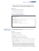
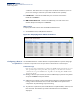
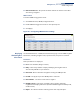
Table Of Contents
- ECS4810-12M Gigabit Ethernet Switch
- How to Use This Guide
- Contents
- Figures
- Tables
- Getting Started
- Web Configuration
- Using the Web Interface
- Basic Management Tasks
- Displaying System Information
- Displaying Hardware/Software Versions
- Configuring Support for Jumbo Frames
- Displaying Bridge Extension Capabilities
- Managing System Files
- Setting the System Clock
- Configuring the Console Port
- Configuring Telnet Settings
- Displaying CPU Utilization
- Displaying Memory Utilization
- Resetting the System
- Interface Configuration
- VLAN Configuration
- Address Table Settings
- Spanning Tree Algorithm
- Congestion Control
- Class of Service
- Quality of Service
- VoIP Traffic Configuration
- Security Measures
- AAA (Authentication, Authorization and Accounting)
- Configuring User Accounts
- Web Authentication
- Network Access (MAC Address Authentication)
- Configuring HTTPS
- Configuring the Secure Shell
- Access Control Lists
- Setting a Time Range
- Showing TCAM Utilization
- Setting the ACL Name and Type
- Configuring a Standard IPv4 ACL
- Configuring an Extended IPv4 ACL
- Configuring a Standard IPv6 ACL
- Configuring an Extended IPv6 ACL
- Configuring a MAC ACL
- Configuring an ARP ACL
- Binding a Port to an Access Control List
- Configuring ACL Mirroring
- Showing ACL Hardware Counters
- ARP Inspection
- Filtering IP Addresses for Management Access
- Configuring Port Security
- Configuring 802.1X Port Authentication
- DoS Protection
- IP Source Guard
- DHCP Snooping
- Basic Administration Protocols
- Configuring Event Logging
- Link Layer Discovery Protocol
- Simple Network Management Protocol
- Configuring Global Settings for SNMP
- Setting the Local Engine ID
- Specifying a Remote Engine ID
- Setting SNMPv3 Views
- Configuring SNMPv3 Groups
- Setting Community Access Strings
- Configuring Local SNMPv3 Users
- Configuring Remote SNMPv3 Users
- Specifying Trap Managers
- Creating SNMP Notification Logs
- Showing SNMP Statistics
- Remote Monitoring
- Switch Clustering
- Ethernet Ring Protection Switching
- Connectivity Fault Management
- Configuring Global Settings for CFM
- Configuring Interfaces for CFM
- Configuring CFM Maintenance Domains
- Configuring CFM Maintenance Associations
- Configuring Maintenance End Points
- Configuring Remote Maintenance End Points
- Transmitting Link Trace Messages
- Transmitting Loop Back Messages
- Transmitting Delay-Measure Requests
- Displaying Local MEPs
- Displaying Details for Local MEPs
- Displaying Local MIPs
- Displaying Remote MEPs
- Displaying Details for Remote MEPs
- Displaying the Link Trace Cache
- Displaying Fault Notification Settings
- Displaying Continuity Check Errors
- OAM Configuration
- UDLD Configuration
- IP Configuration
- IP Services
- Multicast Filtering
- Overview
- Layer 2 IGMP (Snooping and Query for IPv4)
- Configuring IGMP Snooping and Query Parameters
- Specifying Static Interfaces for a Multicast Router
- Assigning Interfaces to Multicast Services
- Setting IGMP Snooping Status per Interface
- Filtering IGMP Query and Report Packets
- Displaying Multicast Groups Discovered by IGMP Snooping
- Displaying IGMP Snooping Statistics
- Filtering and Throttling IGMP Groups
- MLD Snooping (Snooping and Query for IPv6)
- Multicast VLAN Registration for IPv4
- Multicast VLAN Registration for IPv6
- Appendices
- Glossary
- Index

Chapter 13
| Basic Administration Protocols
UDLD Configuration
– 518 –
get through a link and reach the other end, even though some of them
might get dropped during the transmission.)
Since this behavior must be the same on all the neighbors, the sender of
the echoes expects to receive an echo in reply. If the detection process
ends without the proper echo information being received, the link is
considered to be unidirectional.
◆
Aggressive Mode
– Reduces the shut-down delay after loss of bidirectional
connectivity is detected. (Default: Disabled)
UDLD can function in two modes: normal mode and aggressive mode.
■
In normal mode, determination of link status at the end of the detection
process is always based on information received in UDLD messages:
whether that’s information about the exchange of proper neighbor
identification or the absence of such. Hence, albeit bound by a timer,
normal mode determinations are always based on gleaned information,
and as such are “event-based.” If no such information can be obtained (e.g.,
because of a bidirectional loss of connectivity), UDLD follows a
conservative approach to minimize false positives during the detection
process and deems a port to be in “undetermined” state. In other words,
normal mode will shut down a port only if it can explicitly determine that
the associated link is faulty for an extended period of time.
■
In aggressive mode, UDLD will also shut down a port if it loses bidirectional
connectivity with the neighbor for the same extended period of time (as
that mentioned above for normal mode) and subsequently fails repeated
last-resort attempts to re-establish communication with the other end of
the link. This mode of operation assumes that loss of communication with
the neighbor is a meaningful network event in itself, and a symptom of a
serious connectivity problem. Because this type of detection can be event-
less, and lack of information cannot always be associated to an actual
malfunction of the link, this mode is recommended only in certain
scenarios (typically only on point-to-point links where no communication
failure between two neighbors is admissible).
◆
Operation State
– Shows the UDLD operational state (Disabled, Link down,
Link up, Advertisement, Detection, Disabled port, Advertisement - Single
neighbor, Advertisement - Multiple neighbors)
◆
Port State
– Shows the UDLD port state (Unknown, Bidirectional,
Unidirectional, Transmit-to-receive loop, Mismatch with neighbor state
reported, Neighbor's echo is empty)
The state is Unknown if the link is down or not connected to a UDLD-capable
device. The state is Bidirectional if the link has a normal two-way connection to
a UDLD-capable device. All other states indicate mis-wiring.
◆
Message Interval
– The interval between UDLD probe messages used for the
indicated operational state.