
Web Management Guide-R05
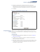
Table Of Contents
- ECS4810-12M Gigabit Ethernet Switch
- How to Use This Guide
- Contents
- Figures
- Tables
- Getting Started
- Web Configuration
- Using the Web Interface
- Basic Management Tasks
- Displaying System Information
- Displaying Hardware/Software Versions
- Configuring Support for Jumbo Frames
- Displaying Bridge Extension Capabilities
- Managing System Files
- Setting the System Clock
- Configuring the Console Port
- Configuring Telnet Settings
- Displaying CPU Utilization
- Displaying Memory Utilization
- Resetting the System
- Interface Configuration
- VLAN Configuration
- Address Table Settings
- Spanning Tree Algorithm
- Congestion Control
- Class of Service
- Quality of Service
- VoIP Traffic Configuration
- Security Measures
- AAA (Authentication, Authorization and Accounting)
- Configuring User Accounts
- Web Authentication
- Network Access (MAC Address Authentication)
- Configuring HTTPS
- Configuring the Secure Shell
- Access Control Lists
- Setting a Time Range
- Showing TCAM Utilization
- Setting the ACL Name and Type
- Configuring a Standard IPv4 ACL
- Configuring an Extended IPv4 ACL
- Configuring a Standard IPv6 ACL
- Configuring an Extended IPv6 ACL
- Configuring a MAC ACL
- Configuring an ARP ACL
- Binding a Port to an Access Control List
- Configuring ACL Mirroring
- Showing ACL Hardware Counters
- ARP Inspection
- Filtering IP Addresses for Management Access
- Configuring Port Security
- Configuring 802.1X Port Authentication
- DoS Protection
- IP Source Guard
- DHCP Snooping
- Basic Administration Protocols
- Configuring Event Logging
- Link Layer Discovery Protocol
- Simple Network Management Protocol
- Configuring Global Settings for SNMP
- Setting the Local Engine ID
- Specifying a Remote Engine ID
- Setting SNMPv3 Views
- Configuring SNMPv3 Groups
- Setting Community Access Strings
- Configuring Local SNMPv3 Users
- Configuring Remote SNMPv3 Users
- Specifying Trap Managers
- Creating SNMP Notification Logs
- Showing SNMP Statistics
- Remote Monitoring
- Switch Clustering
- Ethernet Ring Protection Switching
- Connectivity Fault Management
- Configuring Global Settings for CFM
- Configuring Interfaces for CFM
- Configuring CFM Maintenance Domains
- Configuring CFM Maintenance Associations
- Configuring Maintenance End Points
- Configuring Remote Maintenance End Points
- Transmitting Link Trace Messages
- Transmitting Loop Back Messages
- Transmitting Delay-Measure Requests
- Displaying Local MEPs
- Displaying Details for Local MEPs
- Displaying Local MIPs
- Displaying Remote MEPs
- Displaying Details for Remote MEPs
- Displaying the Link Trace Cache
- Displaying Fault Notification Settings
- Displaying Continuity Check Errors
- OAM Configuration
- UDLD Configuration
- IP Configuration
- IP Services
- Multicast Filtering
- Overview
- Layer 2 IGMP (Snooping and Query for IPv4)
- Configuring IGMP Snooping and Query Parameters
- Specifying Static Interfaces for a Multicast Router
- Assigning Interfaces to Multicast Services
- Setting IGMP Snooping Status per Interface
- Filtering IGMP Query and Report Packets
- Displaying Multicast Groups Discovered by IGMP Snooping
- Displaying IGMP Snooping Statistics
- Filtering and Throttling IGMP Groups
- MLD Snooping (Snooping and Query for IPv6)
- Multicast VLAN Registration for IPv4
- Multicast VLAN Registration for IPv6
- Appendices
- Glossary
- Index

Chapter 13
| Basic Administration Protocols
Connectivity Fault Management
– 474 –
4.
Enter a static list of MEPs assigned to other devices within the same
maintenance association using the Remote MEP List (see "Configuring Remote
Maintenance End Points"). This allows CFM to automatically verify the
functionality of these remote end points by cross-checking the static list
configured on this device against information learned through continuity
check messages.
5.
Enable CFM globally on the switch using the Configure Global screen (see
"Configuring Global Settings for CFM").
6.
Enable CFM on the local MEPs using the Configure Interface screen (see
"Configuring Interfaces for CFM").
7.
Enable continuity check and cross-check operations, and configure AIS
parameters using the Configure MA – Configure Details screen (see
"Configuring CFM Maintenance Associations").
Other configuration changes may be required for your particular environment,
such as adjusting the interval at which continuity check messages are sent (see
"Configuring CFM Maintenance Associations"), or setting the start-up delay for the
cross-check operation (see "Configuring Global Settings for CFM"). You can also
enable SNMP traps for events discovered by continuity check messages or cross-
check messages (see "Configuring Global Settings for CFM").
Configuring Global
Settings for CFM
Use the Administration > CFM (Configure Global) page to configure global settings
for CFM, such as enabling the CFM process on the switch, setting the start-up delay
for cross-check operations, configuring parameters for the link trace cache, and
enabling traps for events discovered by continuity check messages or cross-check
messages.
Parameters
These parameters are displayed:
Global Configuration
◆
CFM Status
– Enables CFM processing globally on the switch.
(Default: Enabled)
To avoid generating an excessive number of traps, the complete CFM
maintenance structure and process parameters should be configured prior to
enabling CFM processing globally on the switch. Specifically, the maintenance
domains, maintenance associations, and maintenance end-points (MEPs)
should be configured on each participating bridge using the Configure MD
page (see "Configuring CFM Maintenance Domains"), Configure MA page (see
"Configuring CFM Maintenance Associations"), and the Configure MEP page
(see "Configuring Maintenance End Points").
When CFM is enabled, hardware resources are allocated for CFM processing.