
Web Management Guide-R05
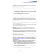
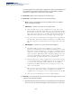
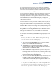
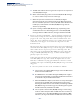
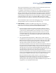
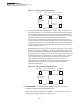
Table Of Contents
- ECS4810-12M Gigabit Ethernet Switch
- How to Use This Guide
- Contents
- Figures
- Tables
- Getting Started
- Web Configuration
- Using the Web Interface
- Basic Management Tasks
- Displaying System Information
- Displaying Hardware/Software Versions
- Configuring Support for Jumbo Frames
- Displaying Bridge Extension Capabilities
- Managing System Files
- Setting the System Clock
- Configuring the Console Port
- Configuring Telnet Settings
- Displaying CPU Utilization
- Displaying Memory Utilization
- Resetting the System
- Interface Configuration
- VLAN Configuration
- Address Table Settings
- Spanning Tree Algorithm
- Congestion Control
- Class of Service
- Quality of Service
- VoIP Traffic Configuration
- Security Measures
- AAA (Authentication, Authorization and Accounting)
- Configuring User Accounts
- Web Authentication
- Network Access (MAC Address Authentication)
- Configuring HTTPS
- Configuring the Secure Shell
- Access Control Lists
- Setting a Time Range
- Showing TCAM Utilization
- Setting the ACL Name and Type
- Configuring a Standard IPv4 ACL
- Configuring an Extended IPv4 ACL
- Configuring a Standard IPv6 ACL
- Configuring an Extended IPv6 ACL
- Configuring a MAC ACL
- Configuring an ARP ACL
- Binding a Port to an Access Control List
- Configuring ACL Mirroring
- Showing ACL Hardware Counters
- ARP Inspection
- Filtering IP Addresses for Management Access
- Configuring Port Security
- Configuring 802.1X Port Authentication
- DoS Protection
- IP Source Guard
- DHCP Snooping
- Basic Administration Protocols
- Configuring Event Logging
- Link Layer Discovery Protocol
- Simple Network Management Protocol
- Configuring Global Settings for SNMP
- Setting the Local Engine ID
- Specifying a Remote Engine ID
- Setting SNMPv3 Views
- Configuring SNMPv3 Groups
- Setting Community Access Strings
- Configuring Local SNMPv3 Users
- Configuring Remote SNMPv3 Users
- Specifying Trap Managers
- Creating SNMP Notification Logs
- Showing SNMP Statistics
- Remote Monitoring
- Switch Clustering
- Ethernet Ring Protection Switching
- Connectivity Fault Management
- Configuring Global Settings for CFM
- Configuring Interfaces for CFM
- Configuring CFM Maintenance Domains
- Configuring CFM Maintenance Associations
- Configuring Maintenance End Points
- Configuring Remote Maintenance End Points
- Transmitting Link Trace Messages
- Transmitting Loop Back Messages
- Transmitting Delay-Measure Requests
- Displaying Local MEPs
- Displaying Details for Local MEPs
- Displaying Local MIPs
- Displaying Remote MEPs
- Displaying Details for Remote MEPs
- Displaying the Link Trace Cache
- Displaying Fault Notification Settings
- Displaying Continuity Check Errors
- OAM Configuration
- UDLD Configuration
- IP Configuration
- IP Services
- Multicast Filtering
- Overview
- Layer 2 IGMP (Snooping and Query for IPv4)
- Configuring IGMP Snooping and Query Parameters
- Specifying Static Interfaces for a Multicast Router
- Assigning Interfaces to Multicast Services
- Setting IGMP Snooping Status per Interface
- Filtering IGMP Query and Report Packets
- Displaying Multicast Groups Discovered by IGMP Snooping
- Displaying IGMP Snooping Statistics
- Filtering and Throttling IGMP Groups
- MLD Snooping (Snooping and Query for IPv6)
- Multicast VLAN Registration for IPv4
- Multicast VLAN Registration for IPv6
- Appendices
- Glossary
- Index

Chapter 13
| Basic Administration Protocols
Ethernet Ring Protection Switching
– 460 –
Figure 291: Sub-ring with Virtual Channel
■
Sub-ring without R-APS Virtual Channel – Under certain circumstances it
may not be desirable to use a virtual channel to interconnect the sub-ring
over an arbitrary Ethernet network. In this situation, the R-APS messages
are terminated on the interconnection points. Since the sub-ring does not
provide an R-APS channel nor R-APS virtual channel beyond the
interconnection points, R-APS channel blocking is not employed on the
normal ring links to avoid channel segmentation. As a result, a failure at any
ring link in the sub-ring will cause the R-APS channel of the sub-ring to be
segmented, thus preventing R-APS message exchange between some of
the sub-ring’s ring nodes.
No R-APS messages are inserted or extracted by other rings or sub- rings at
the interconnection nodes where a sub-ring is attached. Hence there is no
need for either additional bandwidth or for different VIDs/Ring IDs for the
ring interconnection. Furthermore, protection switching time for a sub-ring
is independent from the configuration or topology of the interconnected
rings. In addition, this option always ensures that an interconnected
network forms a tree topology regardless of its interconnection
configuration. This means that it is not necessary to take precautions
against forming a loop which is potentially composed of a whole
interconnected network.
Figure 292: Sub-ring without Virtual Channel
◆
R-APS Def MAC
– Sets the switch’s MAC address to be used as the node
identifier in R-APS messages. (Default: Enabled)
When ring nodes running ERPSv1 and ERPSv2 co-exist on the same ring, the
Ring ID of each ring node must be configured as “1”.
Sub-ring
with Virtual
Channel
Virtual
Channel
RPL Port
Interconnection Node
Ring Node
Major Ring
Sub-ring
with Virtual
Channel
RPL Port
Interconnection Node
Ring Node
Major Ring