
Web Management Guide-R05


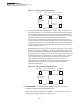
Table Of Contents
- ECS4810-12M Gigabit Ethernet Switch
- How to Use This Guide
- Contents
- Figures
- Tables
- Getting Started
- Web Configuration
- Using the Web Interface
- Basic Management Tasks
- Displaying System Information
- Displaying Hardware/Software Versions
- Configuring Support for Jumbo Frames
- Displaying Bridge Extension Capabilities
- Managing System Files
- Setting the System Clock
- Configuring the Console Port
- Configuring Telnet Settings
- Displaying CPU Utilization
- Displaying Memory Utilization
- Resetting the System
- Interface Configuration
- VLAN Configuration
- Address Table Settings
- Spanning Tree Algorithm
- Congestion Control
- Class of Service
- Quality of Service
- VoIP Traffic Configuration
- Security Measures
- AAA (Authentication, Authorization and Accounting)
- Configuring User Accounts
- Web Authentication
- Network Access (MAC Address Authentication)
- Configuring HTTPS
- Configuring the Secure Shell
- Access Control Lists
- Setting a Time Range
- Showing TCAM Utilization
- Setting the ACL Name and Type
- Configuring a Standard IPv4 ACL
- Configuring an Extended IPv4 ACL
- Configuring a Standard IPv6 ACL
- Configuring an Extended IPv6 ACL
- Configuring a MAC ACL
- Configuring an ARP ACL
- Binding a Port to an Access Control List
- Configuring ACL Mirroring
- Showing ACL Hardware Counters
- ARP Inspection
- Filtering IP Addresses for Management Access
- Configuring Port Security
- Configuring 802.1X Port Authentication
- DoS Protection
- IP Source Guard
- DHCP Snooping
- Basic Administration Protocols
- Configuring Event Logging
- Link Layer Discovery Protocol
- Simple Network Management Protocol
- Configuring Global Settings for SNMP
- Setting the Local Engine ID
- Specifying a Remote Engine ID
- Setting SNMPv3 Views
- Configuring SNMPv3 Groups
- Setting Community Access Strings
- Configuring Local SNMPv3 Users
- Configuring Remote SNMPv3 Users
- Specifying Trap Managers
- Creating SNMP Notification Logs
- Showing SNMP Statistics
- Remote Monitoring
- Switch Clustering
- Ethernet Ring Protection Switching
- Connectivity Fault Management
- Configuring Global Settings for CFM
- Configuring Interfaces for CFM
- Configuring CFM Maintenance Domains
- Configuring CFM Maintenance Associations
- Configuring Maintenance End Points
- Configuring Remote Maintenance End Points
- Transmitting Link Trace Messages
- Transmitting Loop Back Messages
- Transmitting Delay-Measure Requests
- Displaying Local MEPs
- Displaying Details for Local MEPs
- Displaying Local MIPs
- Displaying Remote MEPs
- Displaying Details for Remote MEPs
- Displaying the Link Trace Cache
- Displaying Fault Notification Settings
- Displaying Continuity Check Errors
- OAM Configuration
- UDLD Configuration
- IP Configuration
- IP Services
- Multicast Filtering
- Overview
- Layer 2 IGMP (Snooping and Query for IPv4)
- Configuring IGMP Snooping and Query Parameters
- Specifying Static Interfaces for a Multicast Router
- Assigning Interfaces to Multicast Services
- Setting IGMP Snooping Status per Interface
- Filtering IGMP Query and Report Packets
- Displaying Multicast Groups Discovered by IGMP Snooping
- Displaying IGMP Snooping Statistics
- Filtering and Throttling IGMP Groups
- MLD Snooping (Snooping and Query for IPv6)
- Multicast VLAN Registration for IPv4
- Multicast VLAN Registration for IPv6
- Appendices
- Glossary
- Index

Chapter 13
| Basic Administration Protocols
Ethernet Ring Protection Switching
– 454 –
Once the ring has been activated, the configuration of the control VLAN cannot
be modified. Use the Admin Status parameter to stop the ERPS ring before
making any configuration changes to the control VLAN.
◆
Node State
– Refer to the parameters for the Show page.
◆
Node Type
– Shows ERPS node type as one of the following:
■
None
– Node is neither Ring Protection Link (RPL) owner nor neighbor.
(This is the default setting.)
■
RPL Owner
– Specifies a ring node to be the RPL owner.
■
Only one RPL owner can be configured on a ring. The owner
blocks traffic on the RPL during Idle state, and unblocks it during
Protection state (that is, when a signal fault is detected on the
ring or the protection state is enabled with the Forced Switch or
Manual Switch commands on the Configure Operation page).
■
The east and west connections to the ring must be specified for
all ring nodes. When this switch is configured as the RPL owner,
the west ring port is automatically set as being connected to the
RPL.
■
RPL Neighbor
– Specifies a ring node to be the RPL neighbor.
■
The RPL neighbor node, when configured, is a ring node
adjacent to the RPL that is responsible for blocking its end of the
RPL under normal conditions (i.e., the ring is established and no
requests are present in the ring) in addition to the block at the
other end by the RPL Owner Node. The RPL neighbor node may
participate in blocking or unblocking its end of the RPL, but is
not responsible for activating the reversion behavior.
■
Only one RPL owner can be configured on a ring. If the switch is
set as the RPL owner for an ERPS domain, the west ring port is
set as one end of the RPL. If the switch is set as the RPL
neighbor for an ERPS domain, the east ring port is set as the
other end of the RPL.
■
The east and west connections to the ring must be specified for
all ring nodes. When this switch is configured as the RPL
neighbor, the east ring port is set as being connected to the RPL.
■
Note that is not mandatory to declare a RPL neighbor.
◆
Revertive
– Sets the method of recovery to Idle State through revertive or non-
revertive mode. (Default: Enabled)
■
Revertive behavior allows the switch to automatically return the RPL from
Protection state to Idle state through the exchange of protocol messages.