
Web Management Guide-R05
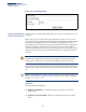
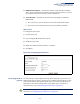
Table Of Contents
- ECS4810-12M Gigabit Ethernet Switch
- How to Use This Guide
- Contents
- Figures
- Tables
- Getting Started
- Web Configuration
- Using the Web Interface
- Basic Management Tasks
- Displaying System Information
- Displaying Hardware/Software Versions
- Configuring Support for Jumbo Frames
- Displaying Bridge Extension Capabilities
- Managing System Files
- Setting the System Clock
- Configuring the Console Port
- Configuring Telnet Settings
- Displaying CPU Utilization
- Displaying Memory Utilization
- Resetting the System
- Interface Configuration
- VLAN Configuration
- Address Table Settings
- Spanning Tree Algorithm
- Congestion Control
- Class of Service
- Quality of Service
- VoIP Traffic Configuration
- Security Measures
- AAA (Authentication, Authorization and Accounting)
- Configuring User Accounts
- Web Authentication
- Network Access (MAC Address Authentication)
- Configuring HTTPS
- Configuring the Secure Shell
- Access Control Lists
- Setting a Time Range
- Showing TCAM Utilization
- Setting the ACL Name and Type
- Configuring a Standard IPv4 ACL
- Configuring an Extended IPv4 ACL
- Configuring a Standard IPv6 ACL
- Configuring an Extended IPv6 ACL
- Configuring a MAC ACL
- Configuring an ARP ACL
- Binding a Port to an Access Control List
- Configuring ACL Mirroring
- Showing ACL Hardware Counters
- ARP Inspection
- Filtering IP Addresses for Management Access
- Configuring Port Security
- Configuring 802.1X Port Authentication
- DoS Protection
- IP Source Guard
- DHCP Snooping
- Basic Administration Protocols
- Configuring Event Logging
- Link Layer Discovery Protocol
- Simple Network Management Protocol
- Configuring Global Settings for SNMP
- Setting the Local Engine ID
- Specifying a Remote Engine ID
- Setting SNMPv3 Views
- Configuring SNMPv3 Groups
- Setting Community Access Strings
- Configuring Local SNMPv3 Users
- Configuring Remote SNMPv3 Users
- Specifying Trap Managers
- Creating SNMP Notification Logs
- Showing SNMP Statistics
- Remote Monitoring
- Switch Clustering
- Ethernet Ring Protection Switching
- Connectivity Fault Management
- Configuring Global Settings for CFM
- Configuring Interfaces for CFM
- Configuring CFM Maintenance Domains
- Configuring CFM Maintenance Associations
- Configuring Maintenance End Points
- Configuring Remote Maintenance End Points
- Transmitting Link Trace Messages
- Transmitting Loop Back Messages
- Transmitting Delay-Measure Requests
- Displaying Local MEPs
- Displaying Details for Local MEPs
- Displaying Local MIPs
- Displaying Remote MEPs
- Displaying Details for Remote MEPs
- Displaying the Link Trace Cache
- Displaying Fault Notification Settings
- Displaying Continuity Check Errors
- OAM Configuration
- UDLD Configuration
- IP Configuration
- IP Services
- Multicast Filtering
- Overview
- Layer 2 IGMP (Snooping and Query for IPv4)
- Configuring IGMP Snooping and Query Parameters
- Specifying Static Interfaces for a Multicast Router
- Assigning Interfaces to Multicast Services
- Setting IGMP Snooping Status per Interface
- Filtering IGMP Query and Report Packets
- Displaying Multicast Groups Discovered by IGMP Snooping
- Displaying IGMP Snooping Statistics
- Filtering and Throttling IGMP Groups
- MLD Snooping (Snooping and Query for IPv6)
- Multicast VLAN Registration for IPv4
- Multicast VLAN Registration for IPv6
- Appendices
- Glossary
- Index

Chapter 12
| Security Measures
Configuring the Secure Shell
– 305 –
3.
Import Client’s Public Key to the Switch – See “Importing User Public Keys” on
page 309 to copy a file containing the public key for all the SSH client’s granted
management access to the switch. (Note that these clients must be configured
locally on the switch via the User Accounts page as described on page 286.) The
clients are subsequently authenticated using these keys. The current firmware
only accepts public key files based on standard UNIX format as shown in the
following example for an RSA Version 1 key:
1024 35
134108168560989392104094492015542534763164192187295892114317388005553616163105
177594083868631109291232226828519254374603100937187721199696317813662774141689
851320491172048303392543241016379975923714490119380060902539484084827178194372
288402533115952134861022902978982721353267131629432532818915045306393916643
steve@192.168.1.19
4.
Set the Optional Parameters – On the SSH Settings page, configure the optional
parameters, including the authentication timeout, the number of retries, and
the server key size.
5.
Enable SSH Service – On the SSH Settings page, enable the SSH server on the
switch.
6.
Authentication – One of the following authentication methods is employed:
Password Authentication (for SSH v1.5 or V2 Clients)
a.
The client sends its password to the server.
b.
The switch compares the client's password to those stored in memory.
c.
If a match is found, the connection is allowed.
Note:
To use SSH with only password authentication, the host public key must still
be given to the client, either during initial connection or manually entered into the
known host file. However, you do not need to configure the client’s keys.
Public Key Authentication – When an SSH client attempts to contact the switch,
the SSH server uses the host key pair to negotiate a session key and encryption
method. Only clients that have a private key corresponding to the public keys
stored on the switch can access it. The following exchanges take place during
this process:
Authenticating SSH v1.5 Clients
a.
The client sends its RSA public key to the switch.
b.
The switch compares the client's public key to those stored in memory.
c.
If a match is found, the switch uses its secret key to generate a random
256-bit string as a challenge, encrypts this string with the user’s public
key, and sends it to the client.
d.
The client uses its private key to decrypt the challenge string, computes
the MD5 checksum, and sends the checksum back to the switch.