
Web Management Guide-R05
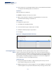
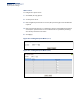
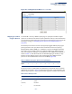
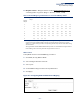
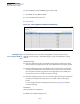
Table Of Contents
- ECS4810-12M Gigabit Ethernet Switch
- How to Use This Guide
- Contents
- Figures
- Tables
- Getting Started
- Web Configuration
- Using the Web Interface
- Basic Management Tasks
- Displaying System Information
- Displaying Hardware/Software Versions
- Configuring Support for Jumbo Frames
- Displaying Bridge Extension Capabilities
- Managing System Files
- Setting the System Clock
- Configuring the Console Port
- Configuring Telnet Settings
- Displaying CPU Utilization
- Displaying Memory Utilization
- Resetting the System
- Interface Configuration
- VLAN Configuration
- Address Table Settings
- Spanning Tree Algorithm
- Congestion Control
- Class of Service
- Quality of Service
- VoIP Traffic Configuration
- Security Measures
- AAA (Authentication, Authorization and Accounting)
- Configuring User Accounts
- Web Authentication
- Network Access (MAC Address Authentication)
- Configuring HTTPS
- Configuring the Secure Shell
- Access Control Lists
- Setting a Time Range
- Showing TCAM Utilization
- Setting the ACL Name and Type
- Configuring a Standard IPv4 ACL
- Configuring an Extended IPv4 ACL
- Configuring a Standard IPv6 ACL
- Configuring an Extended IPv6 ACL
- Configuring a MAC ACL
- Configuring an ARP ACL
- Binding a Port to an Access Control List
- Configuring ACL Mirroring
- Showing ACL Hardware Counters
- ARP Inspection
- Filtering IP Addresses for Management Access
- Configuring Port Security
- Configuring 802.1X Port Authentication
- DoS Protection
- IP Source Guard
- DHCP Snooping
- Basic Administration Protocols
- Configuring Event Logging
- Link Layer Discovery Protocol
- Simple Network Management Protocol
- Configuring Global Settings for SNMP
- Setting the Local Engine ID
- Specifying a Remote Engine ID
- Setting SNMPv3 Views
- Configuring SNMPv3 Groups
- Setting Community Access Strings
- Configuring Local SNMPv3 Users
- Configuring Remote SNMPv3 Users
- Specifying Trap Managers
- Creating SNMP Notification Logs
- Showing SNMP Statistics
- Remote Monitoring
- Switch Clustering
- Ethernet Ring Protection Switching
- Connectivity Fault Management
- Configuring Global Settings for CFM
- Configuring Interfaces for CFM
- Configuring CFM Maintenance Domains
- Configuring CFM Maintenance Associations
- Configuring Maintenance End Points
- Configuring Remote Maintenance End Points
- Transmitting Link Trace Messages
- Transmitting Loop Back Messages
- Transmitting Delay-Measure Requests
- Displaying Local MEPs
- Displaying Details for Local MEPs
- Displaying Local MIPs
- Displaying Remote MEPs
- Displaying Details for Remote MEPs
- Displaying the Link Trace Cache
- Displaying Fault Notification Settings
- Displaying Continuity Check Errors
- OAM Configuration
- UDLD Configuration
- IP Configuration
- IP Services
- Multicast Filtering
- Overview
- Layer 2 IGMP (Snooping and Query for IPv4)
- Configuring IGMP Snooping and Query Parameters
- Specifying Static Interfaces for a Multicast Router
- Assigning Interfaces to Multicast Services
- Setting IGMP Snooping Status per Interface
- Filtering IGMP Query and Report Packets
- Displaying Multicast Groups Discovered by IGMP Snooping
- Displaying IGMP Snooping Statistics
- Filtering and Throttling IGMP Groups
- MLD Snooping (Snooping and Query for IPv6)
- Multicast VLAN Registration for IPv4
- Multicast VLAN Registration for IPv6
- Appendices
- Glossary
- Index

Chapter 9
| Class of Service
Layer 3/4 Priority Settings
– 238 –
Because different priority information may be contained in the traffic, this switch
maps priority values to the output queues in the following manner – The
precedence for priority mapping is DSCP Priority and then Default Port Priority.
Note:
The default settings used for mapping priority values from ingress traffic to
internal DSCP values are used to determine the hardware queues used for egress
traffic, not to replace the priority values. These defaults are designed to optimize
priority services for the majority of network applications. It should not be necessary
to modify any of the default settings, unless a queuing problem occurs with a
particular application.
Mapping Ingress DSCP
Values to Internal
DSCP Values
Use the Traffic > Priority > DSCP to DSCP page to map DSCP values in incoming
packets to per-hop behavior and drop precedence values for internal priority
processing.
The DSCP is six bits wide, allowing coding for up to 64 different forwarding
behaviors. The DSCP replaces the ToS bits, but it retains backward compatibility
with the three precedence bits so that non-DSCP compliant, ToS-enabled devices,
will not conflict with the DSCP mapping. Based on network policies, different kinds
of traffic can be marked for different kinds of forwarding.
Command Usage
◆
Enter per-hop behavior and drop precedence for any of the DSCP values 0 - 63.
◆
This map is only used when the priority mapping mode is set to DSCP (see
page 240), and the ingress packet type is IPv4. Any attempt to configure the
DSCP mutation map will not be accepted by the switch, unless the trust mode
has been set to DSCP.
◆
Two QoS domains can have different DSCP definitions, so the DSCP-to-PHB/
Drop Precedence mutation map can be used to modify one set of DSCP values
to match the definition of another domain. The mutation map should be
applied at the receiving port (ingress mutation) at the boundary of a QoS
administrative domain.
Parameters
These parameters are displayed:
◆
Port
– Specifies a port.
◆
DSCP
– DSCP value in ingress packets. (Range: 0-63)
◆
PHB
– Per-hop behavior, or the priority used for this router hop. (Range: 0-7)