
Web Management Guide-R05
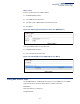
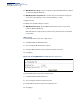


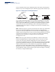
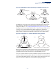
Table Of Contents
- ECS4810-12M Gigabit Ethernet Switch
- How to Use This Guide
- Contents
- Figures
- Tables
- Getting Started
- Web Configuration
- Using the Web Interface
- Basic Management Tasks
- Displaying System Information
- Displaying Hardware/Software Versions
- Configuring Support for Jumbo Frames
- Displaying Bridge Extension Capabilities
- Managing System Files
- Setting the System Clock
- Configuring the Console Port
- Configuring Telnet Settings
- Displaying CPU Utilization
- Displaying Memory Utilization
- Resetting the System
- Interface Configuration
- VLAN Configuration
- Address Table Settings
- Spanning Tree Algorithm
- Congestion Control
- Class of Service
- Quality of Service
- VoIP Traffic Configuration
- Security Measures
- AAA (Authentication, Authorization and Accounting)
- Configuring User Accounts
- Web Authentication
- Network Access (MAC Address Authentication)
- Configuring HTTPS
- Configuring the Secure Shell
- Access Control Lists
- Setting a Time Range
- Showing TCAM Utilization
- Setting the ACL Name and Type
- Configuring a Standard IPv4 ACL
- Configuring an Extended IPv4 ACL
- Configuring a Standard IPv6 ACL
- Configuring an Extended IPv6 ACL
- Configuring a MAC ACL
- Configuring an ARP ACL
- Binding a Port to an Access Control List
- Configuring ACL Mirroring
- Showing ACL Hardware Counters
- ARP Inspection
- Filtering IP Addresses for Management Access
- Configuring Port Security
- Configuring 802.1X Port Authentication
- DoS Protection
- IP Source Guard
- DHCP Snooping
- Basic Administration Protocols
- Configuring Event Logging
- Link Layer Discovery Protocol
- Simple Network Management Protocol
- Configuring Global Settings for SNMP
- Setting the Local Engine ID
- Specifying a Remote Engine ID
- Setting SNMPv3 Views
- Configuring SNMPv3 Groups
- Setting Community Access Strings
- Configuring Local SNMPv3 Users
- Configuring Remote SNMPv3 Users
- Specifying Trap Managers
- Creating SNMP Notification Logs
- Showing SNMP Statistics
- Remote Monitoring
- Switch Clustering
- Ethernet Ring Protection Switching
- Connectivity Fault Management
- Configuring Global Settings for CFM
- Configuring Interfaces for CFM
- Configuring CFM Maintenance Domains
- Configuring CFM Maintenance Associations
- Configuring Maintenance End Points
- Configuring Remote Maintenance End Points
- Transmitting Link Trace Messages
- Transmitting Loop Back Messages
- Transmitting Delay-Measure Requests
- Displaying Local MEPs
- Displaying Details for Local MEPs
- Displaying Local MIPs
- Displaying Remote MEPs
- Displaying Details for Remote MEPs
- Displaying the Link Trace Cache
- Displaying Fault Notification Settings
- Displaying Continuity Check Errors
- OAM Configuration
- UDLD Configuration
- IP Configuration
- IP Services
- Multicast Filtering
- Overview
- Layer 2 IGMP (Snooping and Query for IPv4)
- Configuring IGMP Snooping and Query Parameters
- Specifying Static Interfaces for a Multicast Router
- Assigning Interfaces to Multicast Services
- Setting IGMP Snooping Status per Interface
- Filtering IGMP Query and Report Packets
- Displaying Multicast Groups Discovered by IGMP Snooping
- Displaying IGMP Snooping Statistics
- Filtering and Throttling IGMP Groups
- MLD Snooping (Snooping and Query for IPv6)
- Multicast VLAN Registration for IPv4
- Multicast VLAN Registration for IPv6
- Appendices
- Glossary
- Index

Chapter 7
| Spanning Tree Algorithm
Configuring Global Settings for STA
– 200 –
Configuring Global Settings for STA
Use the Spanning Tree > STA (Configure Global - Configure) page to configure
global settings for the spanning tree that apply to the entire switch.
Command Usage
◆
Spanning Tree Protocol
3
This option uses RSTP set to STP forced compatibility mode. It uses RSTP for the
internal state machine, but sends only 802.1D BPDUs. This creates one
spanning tree instance for the entire network. If multiple VLANs are
implemented on a network, the path between specific VLAN members may be
inadvertently disabled to prevent network loops, thus isolating group
members. When operating multiple VLANs, we recommend selecting the MSTP
option.
◆
Rapid Spanning Tree Protocol
3
RSTP supports connections to either STP or RSTP nodes by monitoring the
incoming protocol messages and dynamically adjusting the type of protocol
messages the RSTP node transmits, as described below:
■
STP Mode – If the switch receives an 802.1D BPDU (i.e., STP BPDU) after a
port’s migration delay timer expires, the switch assumes it is connected to
an 802.1D bridge and starts using only 802.1D BPDUs.
■
RSTP Mode – If RSTP is using 802.1D BPDUs on a port and receives an RSTP
BPDU after the migration delay expires, RSTP restarts the migration delay
timer and begins using RSTP BPDUs on that port.
◆
Multiple Spanning Tree Protocol
MSTP generates a unique spanning tree for each instance. This provides
multiple pathways across the network, thereby balancing the traffic load,
preventing wide-scale disruption when a bridge node in a single instance fails,
and allowing for faster convergence of a new topology for the failed instance.
■
To allow multiple spanning trees to operate over the network, you must
configure a related set of bridges with the same MSTP configuration,
allowing them to participate in a specific set of spanning tree instances.
■
A spanning tree instance can exist only on bridges that have compatible
VLAN instance assignments.
■
Be careful when switching between spanning tree modes. Changing
modes stops all spanning-tree instances for the previous mode and restarts
the system in the new mode, temporarily disrupting user traffic.
3. STP and RSTP BPDUs are transmitted as untagged frames, and will cross any VLAN
boundaries.