
Web Management Guide-R05
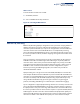
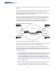
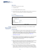
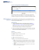
Table Of Contents
- ECS4810-12M Gigabit Ethernet Switch
- How to Use This Guide
- Contents
- Figures
- Tables
- Getting Started
- Web Configuration
- Using the Web Interface
- Basic Management Tasks
- Displaying System Information
- Displaying Hardware/Software Versions
- Configuring Support for Jumbo Frames
- Displaying Bridge Extension Capabilities
- Managing System Files
- Setting the System Clock
- Configuring the Console Port
- Configuring Telnet Settings
- Displaying CPU Utilization
- Displaying Memory Utilization
- Resetting the System
- Interface Configuration
- VLAN Configuration
- Address Table Settings
- Spanning Tree Algorithm
- Congestion Control
- Class of Service
- Quality of Service
- VoIP Traffic Configuration
- Security Measures
- AAA (Authentication, Authorization and Accounting)
- Configuring User Accounts
- Web Authentication
- Network Access (MAC Address Authentication)
- Configuring HTTPS
- Configuring the Secure Shell
- Access Control Lists
- Setting a Time Range
- Showing TCAM Utilization
- Setting the ACL Name and Type
- Configuring a Standard IPv4 ACL
- Configuring an Extended IPv4 ACL
- Configuring a Standard IPv6 ACL
- Configuring an Extended IPv6 ACL
- Configuring a MAC ACL
- Configuring an ARP ACL
- Binding a Port to an Access Control List
- Configuring ACL Mirroring
- Showing ACL Hardware Counters
- ARP Inspection
- Filtering IP Addresses for Management Access
- Configuring Port Security
- Configuring 802.1X Port Authentication
- DoS Protection
- IP Source Guard
- DHCP Snooping
- Basic Administration Protocols
- Configuring Event Logging
- Link Layer Discovery Protocol
- Simple Network Management Protocol
- Configuring Global Settings for SNMP
- Setting the Local Engine ID
- Specifying a Remote Engine ID
- Setting SNMPv3 Views
- Configuring SNMPv3 Groups
- Setting Community Access Strings
- Configuring Local SNMPv3 Users
- Configuring Remote SNMPv3 Users
- Specifying Trap Managers
- Creating SNMP Notification Logs
- Showing SNMP Statistics
- Remote Monitoring
- Switch Clustering
- Ethernet Ring Protection Switching
- Connectivity Fault Management
- Configuring Global Settings for CFM
- Configuring Interfaces for CFM
- Configuring CFM Maintenance Domains
- Configuring CFM Maintenance Associations
- Configuring Maintenance End Points
- Configuring Remote Maintenance End Points
- Transmitting Link Trace Messages
- Transmitting Loop Back Messages
- Transmitting Delay-Measure Requests
- Displaying Local MEPs
- Displaying Details for Local MEPs
- Displaying Local MIPs
- Displaying Remote MEPs
- Displaying Details for Remote MEPs
- Displaying the Link Trace Cache
- Displaying Fault Notification Settings
- Displaying Continuity Check Errors
- OAM Configuration
- UDLD Configuration
- IP Configuration
- IP Services
- Multicast Filtering
- Overview
- Layer 2 IGMP (Snooping and Query for IPv4)
- Configuring IGMP Snooping and Query Parameters
- Specifying Static Interfaces for a Multicast Router
- Assigning Interfaces to Multicast Services
- Setting IGMP Snooping Status per Interface
- Filtering IGMP Query and Report Packets
- Displaying Multicast Groups Discovered by IGMP Snooping
- Displaying IGMP Snooping Statistics
- Filtering and Throttling IGMP Groups
- MLD Snooping (Snooping and Query for IPv6)
- Multicast VLAN Registration for IPv4
- Multicast VLAN Registration for IPv6
- Appendices
- Glossary
- Index

Chapter 5
| VLAN Configuration
IEEE 802.1Q Tunneling
– 167 –
4.
Configure the QinQ tunnel access port to join the SPVLAN as an untagged
member (see “Adding Static Members to VLANs” on page 155).
5.
Configure the SPVLAN ID as the native VID on the QinQ tunnel access port (see
“Adding Static Members to VLANs” on page 155).
6.
Configure the QinQ tunnel uplink port to Uplink mode (see “Adding an
Interface to a QinQ Tunnel” on page 170).
7.
Configure the QinQ tunnel uplink port to join the SPVLAN as a tagged member
(see “Adding Static Members to VLANs” on page 155).
Enabling QinQ
Tunneling on
the Switch
Use the VLAN > Tunnel (Configure Global) page to configure the switch to operate
in IEEE 802.1Q (QinQ) tunneling mode, which is used for passing Layer 2 traffic
across a service provider’s metropolitan area network. You can also globally set the
Tag Protocol Identifier (TPID) value of the tunnel port if the attached client is using
a nonstandard 2-byte ethertype to identify 802.1Q tagged frames.
Parameters
These parameters are displayed:
◆
Tunnel Status
– Sets the switch to QinQ mode. (Default: Disabled)
◆
Ethernet Type
– The Tag Protocol Identifier (TPID) specifies the ethertype of
incoming packets on a tunnel port. (Range: hexadecimal 0800-FFFF;
Default: 8100)
Use this field to set a custom 802.1Q ethertype value for the 802.1Q Tunnel
TPID. This feature allows the switch to interoperate with third-party switches
that do not use the standard 0x8100 ethertype to identify 802.1Q-tagged
frames. For example, if 0x1234 is set as the custom 802.1Q ethertype on a trunk
port, incoming frames containing that ethertype are assigned to the VLAN
contained in the tag following the ethertype field, as they would be with a
standard 802.1Q trunk. Frames arriving on the port containing any other
ethertype are looked upon as untagged frames, and assigned to the native
VLAN of that port.
The specified ethertype only applies to ports configured in Uplink mode (see
“Adding an Interface to a QinQ Tunnel” on page 170). If the port is in normal
mode, the TPID is always 8100. If the port is in Access mode, received packets
are processes as untagged packets.
Avoid using well-known ethertypes for the TPID unless you can eliminate all
side effects. For example, setting the TPID to 0800 hexadecimal (which is used
for IPv4) will interfere with management access through the web interface.