
Web Management Guide-R05
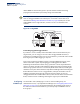
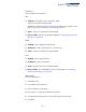
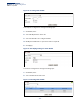
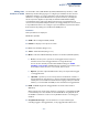
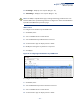
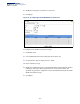
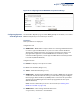
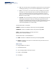
Table Of Contents
- ECS4810-12M Gigabit Ethernet Switch
- How to Use This Guide
- Contents
- Figures
- Tables
- Getting Started
- Web Configuration
- Using the Web Interface
- Basic Management Tasks
- Displaying System Information
- Displaying Hardware/Software Versions
- Configuring Support for Jumbo Frames
- Displaying Bridge Extension Capabilities
- Managing System Files
- Setting the System Clock
- Configuring the Console Port
- Configuring Telnet Settings
- Displaying CPU Utilization
- Displaying Memory Utilization
- Resetting the System
- Interface Configuration
- VLAN Configuration
- Address Table Settings
- Spanning Tree Algorithm
- Congestion Control
- Class of Service
- Quality of Service
- VoIP Traffic Configuration
- Security Measures
- AAA (Authentication, Authorization and Accounting)
- Configuring User Accounts
- Web Authentication
- Network Access (MAC Address Authentication)
- Configuring HTTPS
- Configuring the Secure Shell
- Access Control Lists
- Setting a Time Range
- Showing TCAM Utilization
- Setting the ACL Name and Type
- Configuring a Standard IPv4 ACL
- Configuring an Extended IPv4 ACL
- Configuring a Standard IPv6 ACL
- Configuring an Extended IPv6 ACL
- Configuring a MAC ACL
- Configuring an ARP ACL
- Binding a Port to an Access Control List
- Configuring ACL Mirroring
- Showing ACL Hardware Counters
- ARP Inspection
- Filtering IP Addresses for Management Access
- Configuring Port Security
- Configuring 802.1X Port Authentication
- DoS Protection
- IP Source Guard
- DHCP Snooping
- Basic Administration Protocols
- Configuring Event Logging
- Link Layer Discovery Protocol
- Simple Network Management Protocol
- Configuring Global Settings for SNMP
- Setting the Local Engine ID
- Specifying a Remote Engine ID
- Setting SNMPv3 Views
- Configuring SNMPv3 Groups
- Setting Community Access Strings
- Configuring Local SNMPv3 Users
- Configuring Remote SNMPv3 Users
- Specifying Trap Managers
- Creating SNMP Notification Logs
- Showing SNMP Statistics
- Remote Monitoring
- Switch Clustering
- Ethernet Ring Protection Switching
- Connectivity Fault Management
- Configuring Global Settings for CFM
- Configuring Interfaces for CFM
- Configuring CFM Maintenance Domains
- Configuring CFM Maintenance Associations
- Configuring Maintenance End Points
- Configuring Remote Maintenance End Points
- Transmitting Link Trace Messages
- Transmitting Loop Back Messages
- Transmitting Delay-Measure Requests
- Displaying Local MEPs
- Displaying Details for Local MEPs
- Displaying Local MIPs
- Displaying Remote MEPs
- Displaying Details for Remote MEPs
- Displaying the Link Trace Cache
- Displaying Fault Notification Settings
- Displaying Continuity Check Errors
- OAM Configuration
- UDLD Configuration
- IP Configuration
- IP Services
- Multicast Filtering
- Overview
- Layer 2 IGMP (Snooping and Query for IPv4)
- Configuring IGMP Snooping and Query Parameters
- Specifying Static Interfaces for a Multicast Router
- Assigning Interfaces to Multicast Services
- Setting IGMP Snooping Status per Interface
- Filtering IGMP Query and Report Packets
- Displaying Multicast Groups Discovered by IGMP Snooping
- Displaying IGMP Snooping Statistics
- Filtering and Throttling IGMP Groups
- MLD Snooping (Snooping and Query for IPv6)
- Multicast VLAN Registration for IPv4
- Multicast VLAN Registration for IPv6
- Appendices
- Glossary
- Index

Chapter 5
| VLAN Configuration
IEEE 802.1Q VLANs
– 160 –
■
Join
– The interval between transmitting requests/queries to participate in
a VLAN group. (Range: 20-1000 centiseconds; Default: 20 centiseconds)
■
Leave
– The interval a port waits before leaving a VLAN group. This time
should be set to more than twice the join time. This ensures that after a
Leave or LeaveAll message has been issued, the applicants can rejoin
before the port actually leaves the group. (Range: 60-3000 centiseconds;
Default: 60 centiseconds)
■
LeaveAll
– The interval between sending out a LeaveAll query message for
VLAN group participants and the port leaving the group. This interval
should be considerably larger than the Leave Time to minimize the amount
of traffic generated by nodes rejoining the group. (Range: 500-18000
centiseconds; Default: 1000 centiseconds)
Show Dynamic VLAN – Show VLAN
VLAN ID
– Identifier of a VLAN this switch has joined through GVRP.
VLAN Name –
Name of a VLAN this switch has joined through GVRP.
Status
– Indicates if this VLAN is currently operational.
(Display Values: Enabled, Disabled)
Show Dynamic VLAN – Show VLAN Member
◆
VLAN
– Identifier of a VLAN this switch has joined through GVRP.
◆
Interface
– Displays a list of ports or trunks which have joined the selected
VLAN through GVRP.
Web Interface
To configure GVRP on the switch:
1.
Click VLAN, Dynamic.
2.
Select Configure General from the Step list.
3.
Enable or disable GVRP.
4.
Click Apply.