
Web Management Guide-R05
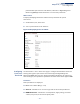
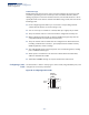
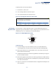
Table Of Contents
- ECS4810-12M Gigabit Ethernet Switch
- How to Use This Guide
- Contents
- Figures
- Tables
- Getting Started
- Web Configuration
- Using the Web Interface
- Basic Management Tasks
- Displaying System Information
- Displaying Hardware/Software Versions
- Configuring Support for Jumbo Frames
- Displaying Bridge Extension Capabilities
- Managing System Files
- Setting the System Clock
- Configuring the Console Port
- Configuring Telnet Settings
- Displaying CPU Utilization
- Displaying Memory Utilization
- Resetting the System
- Interface Configuration
- VLAN Configuration
- Address Table Settings
- Spanning Tree Algorithm
- Congestion Control
- Class of Service
- Quality of Service
- VoIP Traffic Configuration
- Security Measures
- AAA (Authentication, Authorization and Accounting)
- Configuring User Accounts
- Web Authentication
- Network Access (MAC Address Authentication)
- Configuring HTTPS
- Configuring the Secure Shell
- Access Control Lists
- Setting a Time Range
- Showing TCAM Utilization
- Setting the ACL Name and Type
- Configuring a Standard IPv4 ACL
- Configuring an Extended IPv4 ACL
- Configuring a Standard IPv6 ACL
- Configuring an Extended IPv6 ACL
- Configuring a MAC ACL
- Configuring an ARP ACL
- Binding a Port to an Access Control List
- Configuring ACL Mirroring
- Showing ACL Hardware Counters
- ARP Inspection
- Filtering IP Addresses for Management Access
- Configuring Port Security
- Configuring 802.1X Port Authentication
- DoS Protection
- IP Source Guard
- DHCP Snooping
- Basic Administration Protocols
- Configuring Event Logging
- Link Layer Discovery Protocol
- Simple Network Management Protocol
- Configuring Global Settings for SNMP
- Setting the Local Engine ID
- Specifying a Remote Engine ID
- Setting SNMPv3 Views
- Configuring SNMPv3 Groups
- Setting Community Access Strings
- Configuring Local SNMPv3 Users
- Configuring Remote SNMPv3 Users
- Specifying Trap Managers
- Creating SNMP Notification Logs
- Showing SNMP Statistics
- Remote Monitoring
- Switch Clustering
- Ethernet Ring Protection Switching
- Connectivity Fault Management
- Configuring Global Settings for CFM
- Configuring Interfaces for CFM
- Configuring CFM Maintenance Domains
- Configuring CFM Maintenance Associations
- Configuring Maintenance End Points
- Configuring Remote Maintenance End Points
- Transmitting Link Trace Messages
- Transmitting Loop Back Messages
- Transmitting Delay-Measure Requests
- Displaying Local MEPs
- Displaying Details for Local MEPs
- Displaying Local MIPs
- Displaying Remote MEPs
- Displaying Details for Remote MEPs
- Displaying the Link Trace Cache
- Displaying Fault Notification Settings
- Displaying Continuity Check Errors
- OAM Configuration
- UDLD Configuration
- IP Configuration
- IP Services
- Multicast Filtering
- Overview
- Layer 2 IGMP (Snooping and Query for IPv4)
- Configuring IGMP Snooping and Query Parameters
- Specifying Static Interfaces for a Multicast Router
- Assigning Interfaces to Multicast Services
- Setting IGMP Snooping Status per Interface
- Filtering IGMP Query and Report Packets
- Displaying Multicast Groups Discovered by IGMP Snooping
- Displaying IGMP Snooping Statistics
- Filtering and Throttling IGMP Groups
- MLD Snooping (Snooping and Query for IPv6)
- Multicast VLAN Registration for IPv4
- Multicast VLAN Registration for IPv6
- Appendices
- Glossary
- Index

Chapter 4
| Interface Configuration
Port Configuration
– 123 –
■
Trap messages configured by this command are sent to any management
station configured as an SNMP trap manager using the Administration >
SNMP (Configure Trap) page.
Note:
Trap messages for transceiver thresholds are disabled by default. To send a
trap when any of the transceiver’s operational values fall outside of specified
thresholds, use the transceiver-monitor command in the CLI.
Web Interface
To configure threshold values for optical transceivers:
1.
Click Interface, Port, Transceiver.
2.
Select a port from the scroll-down list.
3.
Set the switch to send a trap based on default or manual settings.
4.
Set alarm and warning thresholds if manual configuration is used.
5.
Click Apply.
Figure 43: Configuring Transceiver Thresholds
Performing
Cable Diagnostics
Use the Interface > Port > Cable Test page to test the cable attached to a port. The
cable test will check for any cable faults (short, open, etc.). If a fault is found, the
switch reports the length to the fault. Otherwise, it reports the cable length. It can
be used to determine the quality of the cable, connectors, and terminations.
Problems such as opens, shorts, and cable impedance mismatch can be diagnosed
with this test.
Command Usage
◆
Cable diagnostics are performed using Digital Signal Processing (DSP) test
methods. DSP analyses the cable by sending a pulsed signal into the cable, and
then examining the reflection of that pulse.
◆
Cable diagnostics can only be performed on twisted-pair media.