
Installation Guide
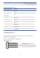

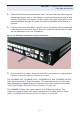
Table Of Contents
- ECS4810-12M Managed 12-Port Gigabit Ethernet Switch
- Compliances and Safety Statements
- About This Guide
- Contents
- Tables
- Figures
- Introduction
- Installing the Switch
- Making Network Connections
- Troubleshooting
- Cables
- Specifications
- Glossary
- Index

C
HAPTER
3
| Making Network Connections
Cable Labeling and Connection Records
– 50 –
switch is connected to a hub, both devices must operate in half-duplex
mode.
2. To interconnect distinct VLANs or IP subnets, you can attach the switch to a
standard Layer 3 router. For network applications that require routing
between dissimilar network types, attach the switch to a multi-protocol
router.
3. As a general rule, the length of fiber optic cable for a single switched link
should not exceed:
■
1000BASE-LX5: 5 km (3.1 miles) for single-mode fiber, duplex fiber
■
1000BASE-LX15: 15 km (6.2 miles) for single-mode fiber, duplex fiber
■
1000BASE-LHX: 40 km (24.9 miles) for single-mode fiber, duplex fiber
■
1000BASE-ZX: 70 km (43.5 miles) for single-mode fiber, duplex fiber
■
100BASE-FX: 20 km (12.4 miles) for single-mode fiber, duplex fiber
However, power budget constraints must also be considered when calculating
the maximum cable length for your specific environment.
CABLE LABELING AND CONNECTION RECORDS
When planning a network installation, it is essential to label the opposing ends of
cables and to record where each cable is connected. Doing so will enable you to
easily locate inter-connected devices, isolate faults and change your topology
without need for unnecessary time consumption.
To best manage the physical implementations of your network, follow these
guidelines:
◆ Clearly label the opposing ends of each cable.
◆ Using your building’s floor plans, draw a map of the location of all network-
connected equipment. For each piece of equipment, identify the devices to
which it is connected.