
Installation Guide
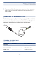

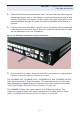
Table Of Contents
- ECS4810-12M Managed 12-Port Gigabit Ethernet Switch
- Compliances and Safety Statements
- About This Guide
- Contents
- Tables
- Figures
- Introduction
- Installing the Switch
- Making Network Connections
- Troubleshooting
- Cables
- Specifications
- Glossary
- Index

C
HAPTER
3
| Making Network Connections
Fiber Optic SFP Devices
– 46 –
Make sure each twisted pair cable does not exceed 100 meters (328 ft) in
length.
3. As each connection is made, the relevant Port LED (on the switch)
corresponding to each port will light green or amber to indicate that the
connection is valid.
FIBER OPTIC SFP DEVICES
An optional Gigabit SFP transceiver (1000BASE-LX5, 1000BASE-LX15,
1000BASE-LHX, or 1000BASE-ZX) or 100BASE-FX SFP transceiver can be used
for a backbone connection between switches, or for connecting to a high-speed
server.
Each single-mode fiber port requires 9/125 micron single-mode fiber optic cable
with an LC connector at both ends. Each multimode fiber optic port requires 50/
125 or 62.5/125 micron multimode fiber optic cabling with an LC connector at
both ends.
1. Remove and keep the LC port’s rubber cover. When not connected to a fiber
cable, the rubber cover should be replaced to protect the optics.
N
OTE
:
Avoid using flow control on a port connected to a hub unless it is
actually required to solve a problem. Otherwise back pressure jamming
signals may degrade overall performance for the segment attached to
the hub.
W
ARNING
:
This switch uses lasers to transmit signals over fiber optic
cable. The lasers are compliant with the requirements of a Class 1
Laser Product and are inherently eye safe in normal operation.
However, you should never look directly at a transmit port when it is
powered on.
N
OTE
:
When selecting a fiber SFP device, considering safety, please
make sure that it can function at a temperature that is not less than the
recommended maximum operational temperature of the product. You
must also use an approved Laser Class 1 SFP transceiver.