
Installation Guide
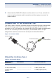
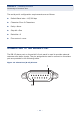

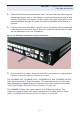
Table Of Contents
- ECS4810-12M Managed 12-Port Gigabit Ethernet Switch
- Compliances and Safety Statements
- About This Guide
- Contents
- Tables
- Figures
- Introduction
- Installing the Switch
- Making Network Connections
- Troubleshooting
- Cables
- Specifications
- Glossary
- Index

– 45 –
3 MAKING NETWORK CONNECTIONS
CONNECTING NETWORK DEVICES
This switch is designed to connect broadband access network devices to
aggregation network devices in the service provider CO. It can connect to
twisted-pair devices through its RJ-45 ports, or to fiber-optic devices through
SFP transceivers.
TWISTED-PAIR DEVICES
Each device requires an unshielded twisted-pair (UTP) cable with RJ-45
connectors at both ends. Use Category 5, 5e or 6 cable for 1000BASE-T
connections.
CABLING GUIDELINES
The RJ-45 ports on the switch support automatic MDI/MDI-X pinout
configuration, so you can use standard straight-through twisted-pair cables to
connect to any other network device (PCs, servers, switches, routers, or hubs).
See "Cables" on page 57 for further information on cabling.
CONNECTING TO PCS, SERVERS, HUBS AND SWITCHES
1. Attach one end of a twisted-pair cable segment to the device’s RJ-45
connector.
2. Attach the other end to an available port on the switch.
C
AUTION
:
Do not plug a phone jack connector into an RJ-45 port. This
will damage the switch. Use only twisted-pair cables with RJ-45
connectors that conform to FCC standards.