
Installation Guide
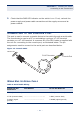
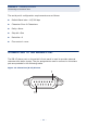
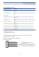

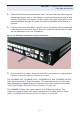
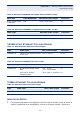
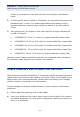
Table Of Contents
- ECS4810-12M Managed 12-Port Gigabit Ethernet Switch
- Compliances and Safety Statements
- About This Guide
- Contents
- Tables
- Figures
- Introduction
- Installing the Switch
- Making Network Connections
- Troubleshooting
- Cables
- Specifications
- Glossary
- Index

C
HAPTER
2
| Installing the Switch
Connecting to the Console Port
– 41 –
5. Check that the PWR LED indicator on the switch is on. If not, recheck the
power supply and power cable connections at the supply source and at
power module.
CONNECTING TO THE CONSOLE PORT
This port is used to connect a console device to the switch through a serial cable.
The console device can be a PC or workstation running a VT-100 terminal
emulator, or a VT-100 terminal. A crossover RJ-45 to DB-9 cable is supplied with
the unit for connecting to the console port, as illustrated below. The pin
assignments used to connect to the serial port are described below.
Figure 13: Console Cable
WIRING MAP FOR SERIAL CABLE
Table 4: Serial Cable Wiring
Switch’s 8-Pin
Serial Port
Null Modem PC’s 9-Pin DTE Port
6 RXD (receive data) <----------------------------- 3 TXD (transmit data)
3 TXD (transmit data) ------------------------------> 2 RXD (receive data)
5 SGND (signal
ground)
------------------------------- 5 SGND (signal ground)
RJ-45 Connector
Console Port
DB-9 Port