
Installation Guide
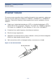

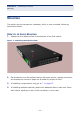

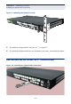
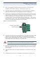
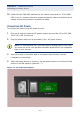
Table Of Contents
- ECS4810-12M Managed 12-Port Gigabit Ethernet Switch
- Compliances and Safety Statements
- About This Guide
- Contents
- Tables
- Figures
- Introduction
- Installing the Switch
- Making Network Connections
- Troubleshooting
- Cables
- Specifications
- Glossary
- Index

C
HAPTER
2
| Installing the Switch
Connecting to a Power Source
– 39 –
3. Use a wire stripper to carefully strip about a half an inch of the outer
insulation off the end of each wire, exposing the copper core.
4. Twist the copper wire strands together to form a tight braid. If possible,
solder the exposed braid of wire together for better conductivity.
5. Connect the external power feed and power ground/return lines to the DC
plug (provided with the switch) as shown in the following figure. The power
leads are labeled on the front of the chassis, above the DC power
connection block. The -48 VDC power feed connects to the “-” pin, and the
ground/return to the “+” pin. Use a small flat-tip screwdriver to loosen the
screws on the power plug and open the wire clamps.
Figure 11: DC Plug Connections
6. Insert the wire leads into the openings shown in the figure below. Each lead
inserted in the power plug must match the lead attached to the power
source. Use the label above the DC power connection block to identify the
appropriate power input and return or ground lines.
7. Push each wire about half an inch into the opening on the plug, and tighten
down the clamp screw securely. You should not be able to pull on the wire
and dislodge it.
8. Insert the power plug in the power receptacle on the left side of the front
panel.
9. At the power source, turn on the power for the feed lines or power bus.
W
ARNING
:
If the power leads are plugged into the wrong holes, the
power supply will not work properly and may damage the switch.
-48 VDC power feed
DC power / ground return