
Installation Guide
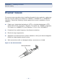

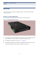

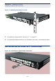
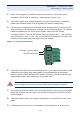
Table Of Contents
- ECS4810-12M Managed 12-Port Gigabit Ethernet Switch
- Compliances and Safety Statements
- About This Guide
- Contents
- Tables
- Figures
- Introduction
- Installing the Switch
- Making Network Connections
- Troubleshooting
- Cables
- Specifications
- Glossary
- Index

C
HAPTER
2
| Installing the Switch
Connecting to a Power Source
– 38 –
CONNECTING TO A POWER SOURCE
This switch supports both AC and DC power supplies.
CONNECTING DC POWER
When using -48 VDC power, an external DC power supply must be connected to
the DC power connector on the left side of the front panel.
To connect the switch to a power source:
1. First verify that the external DC power supply can provide -42 to -56 VDC,
0.6 A minimum.
2. Prepare two wires for the DC power source. Use 10 to 24 AWG stranded
copper wire. Make sure these wires are not plugged into the power source.
W
ARNING
:
Before wiring the DC plug or connecting power to the switch,
ensure that power to the feed lines is turned off at the supply circuit
breaker or disconnected from the power bus.
N
OTE
:
To provide adequate circuit protection between the DC power
supply and the switch, all intermediate wiring and circuitry should be
rated to carry a load at least two times the maximum rating for this
switch, described in "Power Supply" on page 64.
N
OTE
:
The wiring between the DC power supply and the switch must be
stranded copper wire within the range of 10 to 24 AWG.
N
OTE
:
Wiring for the power input terminals on the switch are described
below. Wiring of the DC power supply terminals depends on the
equipment in use on the local site, but should be wired in such a way as
to meet the input requirements shown in "DC Plug Connections" on
page 39. The wiring should also be color coded according to local
standards to ensure that the input power and ground lines can be easily
distinguished.