
Installation Guide

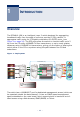
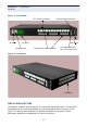
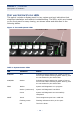
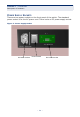
Table Of Contents
- ECS4810-12M Managed 12-Port Gigabit Ethernet Switch
- Compliances and Safety Statements
- About This Guide
- Contents
- Tables
- Figures
- Introduction
- Installing the Switch
- Making Network Connections
- Troubleshooting
- Cables
- Specifications
- Glossary
- Index

– 21 –
FIGURES
Figure 1: Deployment 23
Figure 2: Front Panel 24
Figure 3: Side Panel 24
Figure 4: Port and System LEDs 28
Figure 5: Power Supply Socket 30
Figure 6: RJ-45 Connections 32
Figure 7: Attaching the Adhesive Feet 34
Figure 8: Attaching the Brackets 35
Figure 9: Installing the Switch in a Rack 36
Figure 10: Installing an Optional SFP Transceiver 36
Figure 11: DC Plug Connections 39
Figure 12: AC Power Rececptacle 40
Figure 13: Console Cable 41
Figure 14: Alarm Port (D-15) Pin-Out 42
Figure 15: External Alarm I/O Connections 43
Figure 16: Making Connections to SFP Transceivers 47
Figure 17: RJ-45 Connector Pin Numbers 57
Figure 18: Straight-through Wiring 59
Figure 19: Crossover Wiring 59