
Web Management Guide-R06
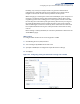
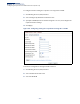
Table Of Contents
- How to Use This Guide
- Contents
- Figures
- Tables
- Getting Started
- Web Configuration
- Using the Web Interface
- Basic Management Tasks
- Displaying System Information
- Displaying Hardware/Software Versions
- Configuring Support for Jumbo Frames
- Displaying Bridge Extension Capabilities
- Managing System Files
- Setting the System Clock
- Configuring the Console Port
- Configuring Telnet Settings
- Displaying CPU Utilization
- Displaying Memory Utilization
- Stacking
- Resetting the System
- Interface Configuration
- VLAN Configuration
- Address Table Settings
- Spanning Tree Algorithm
- Congestion Control
- Class of Service
- Quality of Service
- VoIP Traffic Configuration
- Security Measures
- AAA (Authentication, Authorization and Accounting)
- Configuring User Accounts
- Web Authentication
- Network Access (MAC Address Authentication)
- Configuring HTTPS
- Configuring the Secure Shell
- Access Control Lists
- Setting a Time Range
- Showing TCAM Utilization
- Setting the ACL Name and Type
- Configuring a Standard IPv4 ACL
- Configuring an Extended IPv4 ACL
- Configuring a Standard IPv6 ACL
- Configuring an Extended IPv6 ACL
- Configuring a MAC ACL
- Configuring an ARP ACL
- Binding a Port to an Access Control List
- Configuring ACL Mirroring
- Showing ACL Hardware Counters
- ARP Inspection
- Filtering IP Addresses for Management Access
- Configuring Port Security
- Configuring 802.1X Port Authentication
- DoS Protection
- IPv4 Source Guard
- IPv6 Source Guard
- DHCP Snooping
- Basic Administration Protocols
- Configuring Event Logging
- Link Layer Discovery Protocol
- Power over Ethernet
- Simple Network Management Protocol
- Configuring Global Settings for SNMP
- Setting the Local Engine ID
- Specifying a Remote Engine ID
- Setting SNMPv3 Views
- Configuring SNMPv3 Groups
- Setting Community Access Strings
- Configuring Local SNMPv3 Users
- Configuring Remote SNMPv3 Users
- Specifying Trap Managers
- Creating SNMP Notification Logs
- Showing SNMP Statistics
- Remote Monitoring
- Switch Clustering
- Ethernet Ring Protection Switching
- Connectivity Fault Management
- Configuring Global Settings for CFM
- Configuring Interfaces for CFM
- Configuring CFM Maintenance Domains
- Configuring CFM Maintenance Associations
- Configuring Maintenance End Points
- Configuring Remote Maintenance End Points
- Transmitting Link Trace Messages
- Transmitting Loop Back Messages
- Transmitting Delay-Measure Requests
- Displaying Local MEPs
- Displaying Details for Local MEPs
- Displaying Local MIPs
- Displaying Remote MEPs
- Displaying Details for Remote MEPs
- Displaying the Link Trace Cache
- Displaying Fault Notification Settings
- Displaying Continuity Check Errors
- OAM Configuration
- UDLD Configuration
- Multicast Filtering
- Overview
- Layer 2 IGMP (Snooping and Query for IPv4)
- Configuring IGMP Snooping and Query Parameters
- Specifying Static Interfaces for a Multicast Router
- Assigning Interfaces to Multicast Services
- Setting IGMP Snooping Status per Interface
- Filtering IGMP Query Packets and Multicast Data
- Displaying Multicast Groups Discovered by IGMP Snooping
- Displaying IGMP Snooping Statistics
- Filtering and Throttling IGMP Groups
- MLD Snooping (Snooping and Query for IPv6)
- Layer 3 IGMP (Query used with Multicast Routing)
- Multicast VLAN Registration for IPv4
- Multicast VLAN Registration for IPv6
- IP Configuration
- IP Services
- General IP Routing
- Configuring Router Redundancy
- Unicast Routing
- Overview
- Configuring the Routing Information Protocol
- Configuring General Protocol Settings
- Clearing Entries from the Routing Table
- Specifying Network Interfaces
- Specifying Passive Interfaces
- Specifying Static Neighbors
- Configuring Route Redistribution
- Specifying an Administrative Distance
- Configuring Network Interfaces for RIP
- Displaying RIP Interface Settings
- Displaying Peer Router Information
- Resetting RIP Statistics
- Configuring the Open Shortest Path First Protocol (Version 2)
- Defining Network Areas Based on Addresses
- Configuring General Protocol Settings
- Displaying Administrative Settings and Statistics
- Adding an NSSA or Stub
- Configuring NSSA Settings
- Configuring Stub Settings
- Displaying Information on NSSA and Stub Areas
- Configuring Area Ranges (Route Summarization for ABRs)
- Redistributing External Routes
- Configuring Summary Addresses (for External AS Routes)
- Configuring OSPF Interfaces
- Configuring Virtual Links
- Displaying Link State Database Information
- Displaying Information on Neighboring Routers
- Multicast Routing
- Appendices
- Glossary
- Index

Chapter 19
| Unicast Routing
Configuring the Open Shortest Path First Protocol (Version 2)
– 745 –
Routes are assigned a metric equal to the sum of all metrics for each interface
link in the route.
This router uses a default cost of 1 for all ports. Therefore, if you install a
10 Gigabit module, you need to reset the cost for all of the 1 Gbps ports to a
value greater than 1 to reflect the actual interface bandwidth.
◆ Router Priority – Sets the interface priority for this router. (Range: 0-255;
Default: 1)
This priority determines the designated router (DR) and backup designated
router (BDR) for each OSPF area. The DR forms an active adjacency to all other
routers in the area to exchange routing topology information. If for any reason
the DR fails, the BDR takes over this role.
Set the priority to zero to prevent a router from being elected as a DR or BDR. If
set to any value other than zero, the router with the highest priority becomes
the DR and the router with the next highest priority becomes the BDR. If two or
more routers are set to the same highest priority, the router with the higher ID
will be elected.
If a DR already exists for an area when this interface comes up, the new router
will accept the current DR regardless of its own priority. The DR will not change
until the next time the election process is initiated.
Configure router priority for multi-access networks only and not for point-to-
point networks.
◆ Hello Interval – Sets the interval between sending hello packets on an
interface. This interval must be set to the same value for all routers on the
network. (Range: 1-65535 seconds; Default: 10)
Hello packets are used to inform other routers that the sending router is still
active. Setting the hello interval to a smaller value can reduce the delay in
detecting topological changes, but will increase routing traffic.
◆ Dead Interval – Sets the interval at which hello packets are not seen before
neighbors declare the router down. This interval must be set to the same value
for all routers on the network. (Range: 1-65535 seconds; Default: 40, or 4 times
the Hello Interval)
The dead-interval is advertised in the router's hello packets. It must be a
multiple of hello-interval and be the same for all routers on a specific network.
◆ Transmit Delay – Sets the estimated time to send a link-state update packet
over an interface. (Range: 1-65535 seconds; Default: 1 second)
LSAs have their age incremented by this delay before transmission. You should
consider both the transmission and propagation delays for an interface when
estimating this delay. Set the transmit delay according to link speed, using
larger values for lower-speed links.
If this delay is not added, the time required to transmit an LSA over the link is
not taken into consideration by the routing process. On slow links, the router
may send packets more quickly than devices can receive them. To avoid this