
Web Management Guide-R06
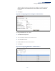
Table Of Contents
- How to Use This Guide
- Contents
- Figures
- Tables
- Getting Started
- Web Configuration
- Using the Web Interface
- Basic Management Tasks
- Displaying System Information
- Displaying Hardware/Software Versions
- Configuring Support for Jumbo Frames
- Displaying Bridge Extension Capabilities
- Managing System Files
- Setting the System Clock
- Configuring the Console Port
- Configuring Telnet Settings
- Displaying CPU Utilization
- Displaying Memory Utilization
- Stacking
- Resetting the System
- Interface Configuration
- VLAN Configuration
- Address Table Settings
- Spanning Tree Algorithm
- Congestion Control
- Class of Service
- Quality of Service
- VoIP Traffic Configuration
- Security Measures
- AAA (Authentication, Authorization and Accounting)
- Configuring User Accounts
- Web Authentication
- Network Access (MAC Address Authentication)
- Configuring HTTPS
- Configuring the Secure Shell
- Access Control Lists
- Setting a Time Range
- Showing TCAM Utilization
- Setting the ACL Name and Type
- Configuring a Standard IPv4 ACL
- Configuring an Extended IPv4 ACL
- Configuring a Standard IPv6 ACL
- Configuring an Extended IPv6 ACL
- Configuring a MAC ACL
- Configuring an ARP ACL
- Binding a Port to an Access Control List
- Configuring ACL Mirroring
- Showing ACL Hardware Counters
- ARP Inspection
- Filtering IP Addresses for Management Access
- Configuring Port Security
- Configuring 802.1X Port Authentication
- DoS Protection
- IPv4 Source Guard
- IPv6 Source Guard
- DHCP Snooping
- Basic Administration Protocols
- Configuring Event Logging
- Link Layer Discovery Protocol
- Power over Ethernet
- Simple Network Management Protocol
- Configuring Global Settings for SNMP
- Setting the Local Engine ID
- Specifying a Remote Engine ID
- Setting SNMPv3 Views
- Configuring SNMPv3 Groups
- Setting Community Access Strings
- Configuring Local SNMPv3 Users
- Configuring Remote SNMPv3 Users
- Specifying Trap Managers
- Creating SNMP Notification Logs
- Showing SNMP Statistics
- Remote Monitoring
- Switch Clustering
- Ethernet Ring Protection Switching
- Connectivity Fault Management
- Configuring Global Settings for CFM
- Configuring Interfaces for CFM
- Configuring CFM Maintenance Domains
- Configuring CFM Maintenance Associations
- Configuring Maintenance End Points
- Configuring Remote Maintenance End Points
- Transmitting Link Trace Messages
- Transmitting Loop Back Messages
- Transmitting Delay-Measure Requests
- Displaying Local MEPs
- Displaying Details for Local MEPs
- Displaying Local MIPs
- Displaying Remote MEPs
- Displaying Details for Remote MEPs
- Displaying the Link Trace Cache
- Displaying Fault Notification Settings
- Displaying Continuity Check Errors
- OAM Configuration
- UDLD Configuration
- Multicast Filtering
- Overview
- Layer 2 IGMP (Snooping and Query for IPv4)
- Configuring IGMP Snooping and Query Parameters
- Specifying Static Interfaces for a Multicast Router
- Assigning Interfaces to Multicast Services
- Setting IGMP Snooping Status per Interface
- Filtering IGMP Query Packets and Multicast Data
- Displaying Multicast Groups Discovered by IGMP Snooping
- Displaying IGMP Snooping Statistics
- Filtering and Throttling IGMP Groups
- MLD Snooping (Snooping and Query for IPv6)
- Layer 3 IGMP (Query used with Multicast Routing)
- Multicast VLAN Registration for IPv4
- Multicast VLAN Registration for IPv6
- IP Configuration
- IP Services
- General IP Routing
- Configuring Router Redundancy
- Unicast Routing
- Overview
- Configuring the Routing Information Protocol
- Configuring General Protocol Settings
- Clearing Entries from the Routing Table
- Specifying Network Interfaces
- Specifying Passive Interfaces
- Specifying Static Neighbors
- Configuring Route Redistribution
- Specifying an Administrative Distance
- Configuring Network Interfaces for RIP
- Displaying RIP Interface Settings
- Displaying Peer Router Information
- Resetting RIP Statistics
- Configuring the Open Shortest Path First Protocol (Version 2)
- Defining Network Areas Based on Addresses
- Configuring General Protocol Settings
- Displaying Administrative Settings and Statistics
- Adding an NSSA or Stub
- Configuring NSSA Settings
- Configuring Stub Settings
- Displaying Information on NSSA and Stub Areas
- Configuring Area Ranges (Route Summarization for ABRs)
- Redistributing External Routes
- Configuring Summary Addresses (for External AS Routes)
- Configuring OSPF Interfaces
- Configuring Virtual Links
- Displaying Link State Database Information
- Displaying Information on Neighboring Routers
- Multicast Routing
- Appendices
- Glossary
- Index

Chapter 15
| IP Configuration
Setting the Switch’s IP Address (IP Version 6)
– 632 –
Configuring IPv6
Interface Settings
Use the IP > IPv6 Configuration (Configure Interface) page to configure general
IPv6 settings for the selected VLAN, including explicit configuration of a link local
interface address, the MTU size, and neighbor discovery protocol settings for
duplicate address detection and the neighbor solicitation interval.
Command Usage
◆ The switch must be configured with a link-local address. The option to explicitly
enable IPv6 creates a link-local address, but will not generate a global IPv6
address. The global unicast address must be manually configured (see
“Configuring an IPv6 Address” on page 636).
◆ IPv6 Neighbor Discovery Protocol supersedes IPv4 Address Resolution Protocol
in IPv6 networks. IPv6 nodes on the same network segment use Neighbor
Discovery to discover each other's presence, to determine each other's link-
layer addresses, to find routers and to maintain reachability information about
the paths to active neighbors. The key parameters used to facilitate this process
are the number of attempts made to verify whether or not a duplicate address
exists on the same network segment, and the interval between neighbor
solicitations used to verify reachability information.
Parameters
These parameters are displayed:
VLAN Mode
◆ VLAN – ID of a configured VLAN which is to be used for management access, or
as a standard interface for a subnet. By default, all ports on the switch are
members of VLAN 1. However, the management station can be attached to a
port belonging to any VLAN, as long as that VLAN has been assigned an IP
address. (Range: 1-4094)
◆ Enable IPv6 Explicitly – Enables IPv6 on an interface and assigns it a link-local
address. Note that when an explicit address is assigned to an interface, IPv6 is
automatically enabled, and cannot be disabled until all assigned addresses
have been removed. (Default: Disabled)
Disabling this parameter does not disable IPv6 for an interface that has been
explicitly configured with an IPv6 address.
◆ MTU – Sets the size of the maximum transmission unit (MTU) for IPv6 packets
sent on an interface. (Range: 1280-65535 bytes; Default: 1500 bytes)
■
The maximum value set in this field cannot exceed the MTU of the physical
interface, which is currently fixed at 1500 bytes.
■
If a non-default value is configured, an MTU option is included in the router
advertisements sent from this device. This option is provided to ensure that
all nodes on a link use the same MTU value in cases where the link MTU is
not otherwise well known.
■
IPv6 routers do not fragment IPv6 packets forwarded from other routers.
However, traffic originating from an end-station connected to an IPv6
router may be fragmented.