
Web Management Guide-R06
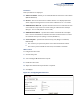
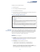
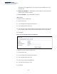
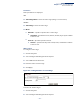
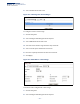
Table Of Contents
- How to Use This Guide
- Contents
- Figures
- Tables
- Getting Started
- Web Configuration
- Using the Web Interface
- Basic Management Tasks
- Displaying System Information
- Displaying Hardware/Software Versions
- Configuring Support for Jumbo Frames
- Displaying Bridge Extension Capabilities
- Managing System Files
- Setting the System Clock
- Configuring the Console Port
- Configuring Telnet Settings
- Displaying CPU Utilization
- Displaying Memory Utilization
- Stacking
- Resetting the System
- Interface Configuration
- VLAN Configuration
- Address Table Settings
- Spanning Tree Algorithm
- Congestion Control
- Class of Service
- Quality of Service
- VoIP Traffic Configuration
- Security Measures
- AAA (Authentication, Authorization and Accounting)
- Configuring User Accounts
- Web Authentication
- Network Access (MAC Address Authentication)
- Configuring HTTPS
- Configuring the Secure Shell
- Access Control Lists
- Setting a Time Range
- Showing TCAM Utilization
- Setting the ACL Name and Type
- Configuring a Standard IPv4 ACL
- Configuring an Extended IPv4 ACL
- Configuring a Standard IPv6 ACL
- Configuring an Extended IPv6 ACL
- Configuring a MAC ACL
- Configuring an ARP ACL
- Binding a Port to an Access Control List
- Configuring ACL Mirroring
- Showing ACL Hardware Counters
- ARP Inspection
- Filtering IP Addresses for Management Access
- Configuring Port Security
- Configuring 802.1X Port Authentication
- DoS Protection
- IPv4 Source Guard
- IPv6 Source Guard
- DHCP Snooping
- Basic Administration Protocols
- Configuring Event Logging
- Link Layer Discovery Protocol
- Power over Ethernet
- Simple Network Management Protocol
- Configuring Global Settings for SNMP
- Setting the Local Engine ID
- Specifying a Remote Engine ID
- Setting SNMPv3 Views
- Configuring SNMPv3 Groups
- Setting Community Access Strings
- Configuring Local SNMPv3 Users
- Configuring Remote SNMPv3 Users
- Specifying Trap Managers
- Creating SNMP Notification Logs
- Showing SNMP Statistics
- Remote Monitoring
- Switch Clustering
- Ethernet Ring Protection Switching
- Connectivity Fault Management
- Configuring Global Settings for CFM
- Configuring Interfaces for CFM
- Configuring CFM Maintenance Domains
- Configuring CFM Maintenance Associations
- Configuring Maintenance End Points
- Configuring Remote Maintenance End Points
- Transmitting Link Trace Messages
- Transmitting Loop Back Messages
- Transmitting Delay-Measure Requests
- Displaying Local MEPs
- Displaying Details for Local MEPs
- Displaying Local MIPs
- Displaying Remote MEPs
- Displaying Details for Remote MEPs
- Displaying the Link Trace Cache
- Displaying Fault Notification Settings
- Displaying Continuity Check Errors
- OAM Configuration
- UDLD Configuration
- Multicast Filtering
- Overview
- Layer 2 IGMP (Snooping and Query for IPv4)
- Configuring IGMP Snooping and Query Parameters
- Specifying Static Interfaces for a Multicast Router
- Assigning Interfaces to Multicast Services
- Setting IGMP Snooping Status per Interface
- Filtering IGMP Query Packets and Multicast Data
- Displaying Multicast Groups Discovered by IGMP Snooping
- Displaying IGMP Snooping Statistics
- Filtering and Throttling IGMP Groups
- MLD Snooping (Snooping and Query for IPv6)
- Layer 3 IGMP (Query used with Multicast Routing)
- Multicast VLAN Registration for IPv4
- Multicast VLAN Registration for IPv6
- IP Configuration
- IP Services
- General IP Routing
- Configuring Router Redundancy
- Unicast Routing
- Overview
- Configuring the Routing Information Protocol
- Configuring General Protocol Settings
- Clearing Entries from the Routing Table
- Specifying Network Interfaces
- Specifying Passive Interfaces
- Specifying Static Neighbors
- Configuring Route Redistribution
- Specifying an Administrative Distance
- Configuring Network Interfaces for RIP
- Displaying RIP Interface Settings
- Displaying Peer Router Information
- Resetting RIP Statistics
- Configuring the Open Shortest Path First Protocol (Version 2)
- Defining Network Areas Based on Addresses
- Configuring General Protocol Settings
- Displaying Administrative Settings and Statistics
- Adding an NSSA or Stub
- Configuring NSSA Settings
- Configuring Stub Settings
- Displaying Information on NSSA and Stub Areas
- Configuring Area Ranges (Route Summarization for ABRs)
- Redistributing External Routes
- Configuring Summary Addresses (for External AS Routes)
- Configuring OSPF Interfaces
- Configuring Virtual Links
- Displaying Link State Database Information
- Displaying Information on Neighboring Routers
- Multicast Routing
- Appendices
- Glossary
- Index

Chapter 12
| Security Measures
Access Control Lists
– 328 –
possible depends on too many factors to be precisely determined. It depends
on the amount of hardware resources reserved at runtime for this purpose.
Auto ACE Compression is a software feature used to compress all the ACEs of an
ACL to utilize hardware resources more efficiency. Without compression, one
ACE would occupy a fixed number of entries in TCAM. So if one ACL includes 25
ACEs, the ACL would need (25 * n) entries in TCAM, where “n” is the fixed
number of TCAM entries needed for one ACE. When compression is employed,
before writing the ACE into TCAM, the software compresses the ACEs to reduce
the number of required TCAM entries. For example, one ACL may include 128
ACEs which classify a continuous IP address range like 192.168.1.0~255. If
compression is disabled, the ACL would occupy (128*n) entries of TCAM, using
up nearly all of the hardware resources. When using compression, the 128 ACEs
are compressed into one ACE classifying the IP address as 192.168.1.0/24,
which requires only “n” entries in TCAM. The above example is an ideal case for
compression. The worst case would be if no any ACE can be compressed, in
which case the used number of TCAM entries would be the same as without
compression. It would also require more time to process the ACEs.
◆ If no matches are found down to the end of the list, the traffic is denied. For this
reason, frequently hit entries should be placed at the top of the list. There is an
implied deny for traffic that is not explicitly permitted. Also, note that a single-
entry ACL with only one deny entry has the effect of denying all traffic. You
should therefore use at least one permit statement in an ACL or all traffic will be
blocked.
Because the switch stops testing after the first match, the order of the
conditions is critical. If no conditions match, the packet will be denied.
The order in which active ACLs are checked is as follows:
1. User-defined rules in IP and MAC ACLs for ingress or egress ports are checked in
parallel.
2. Rules within an ACL are checked in the configured order, from top to bottom.
3. If the result of checking an IP ACL is to permit a packet, but the result of a MAC
ACL on the same packet is to deny it, the packet will be denied (because the
decision to deny a packet has a higher priority for security reasons). A packet
will also be denied if the IP ACL denies it and the MAC ACL accepts it.
Setting a Time Range Use the Security > ACL (Configure Time Range) page to sets a time range during
which ACL functions are applied.
Command Usage
If both an absolute rule and one or more periodic rules are configured for the same
time range (i.e., named entry), that entry will only take effect if the current time is
within the absolute time range and one of the periodic time ranges.