
Web Management Guide-R06
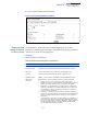
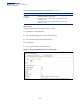
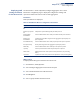
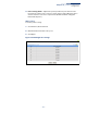
Table Of Contents
- How to Use This Guide
- Contents
- Figures
- Tables
- Getting Started
- Web Configuration
- Using the Web Interface
- Basic Management Tasks
- Displaying System Information
- Displaying Hardware/Software Versions
- Configuring Support for Jumbo Frames
- Displaying Bridge Extension Capabilities
- Managing System Files
- Setting the System Clock
- Configuring the Console Port
- Configuring Telnet Settings
- Displaying CPU Utilization
- Displaying Memory Utilization
- Stacking
- Resetting the System
- Interface Configuration
- VLAN Configuration
- Address Table Settings
- Spanning Tree Algorithm
- Congestion Control
- Class of Service
- Quality of Service
- VoIP Traffic Configuration
- Security Measures
- AAA (Authentication, Authorization and Accounting)
- Configuring User Accounts
- Web Authentication
- Network Access (MAC Address Authentication)
- Configuring HTTPS
- Configuring the Secure Shell
- Access Control Lists
- Setting a Time Range
- Showing TCAM Utilization
- Setting the ACL Name and Type
- Configuring a Standard IPv4 ACL
- Configuring an Extended IPv4 ACL
- Configuring a Standard IPv6 ACL
- Configuring an Extended IPv6 ACL
- Configuring a MAC ACL
- Configuring an ARP ACL
- Binding a Port to an Access Control List
- Configuring ACL Mirroring
- Showing ACL Hardware Counters
- ARP Inspection
- Filtering IP Addresses for Management Access
- Configuring Port Security
- Configuring 802.1X Port Authentication
- DoS Protection
- IPv4 Source Guard
- IPv6 Source Guard
- DHCP Snooping
- Basic Administration Protocols
- Configuring Event Logging
- Link Layer Discovery Protocol
- Power over Ethernet
- Simple Network Management Protocol
- Configuring Global Settings for SNMP
- Setting the Local Engine ID
- Specifying a Remote Engine ID
- Setting SNMPv3 Views
- Configuring SNMPv3 Groups
- Setting Community Access Strings
- Configuring Local SNMPv3 Users
- Configuring Remote SNMPv3 Users
- Specifying Trap Managers
- Creating SNMP Notification Logs
- Showing SNMP Statistics
- Remote Monitoring
- Switch Clustering
- Ethernet Ring Protection Switching
- Connectivity Fault Management
- Configuring Global Settings for CFM
- Configuring Interfaces for CFM
- Configuring CFM Maintenance Domains
- Configuring CFM Maintenance Associations
- Configuring Maintenance End Points
- Configuring Remote Maintenance End Points
- Transmitting Link Trace Messages
- Transmitting Loop Back Messages
- Transmitting Delay-Measure Requests
- Displaying Local MEPs
- Displaying Details for Local MEPs
- Displaying Local MIPs
- Displaying Remote MEPs
- Displaying Details for Remote MEPs
- Displaying the Link Trace Cache
- Displaying Fault Notification Settings
- Displaying Continuity Check Errors
- OAM Configuration
- UDLD Configuration
- Multicast Filtering
- Overview
- Layer 2 IGMP (Snooping and Query for IPv4)
- Configuring IGMP Snooping and Query Parameters
- Specifying Static Interfaces for a Multicast Router
- Assigning Interfaces to Multicast Services
- Setting IGMP Snooping Status per Interface
- Filtering IGMP Query Packets and Multicast Data
- Displaying Multicast Groups Discovered by IGMP Snooping
- Displaying IGMP Snooping Statistics
- Filtering and Throttling IGMP Groups
- MLD Snooping (Snooping and Query for IPv6)
- Layer 3 IGMP (Query used with Multicast Routing)
- Multicast VLAN Registration for IPv4
- Multicast VLAN Registration for IPv6
- IP Configuration
- IP Services
- General IP Routing
- Configuring Router Redundancy
- Unicast Routing
- Overview
- Configuring the Routing Information Protocol
- Configuring General Protocol Settings
- Clearing Entries from the Routing Table
- Specifying Network Interfaces
- Specifying Passive Interfaces
- Specifying Static Neighbors
- Configuring Route Redistribution
- Specifying an Administrative Distance
- Configuring Network Interfaces for RIP
- Displaying RIP Interface Settings
- Displaying Peer Router Information
- Resetting RIP Statistics
- Configuring the Open Shortest Path First Protocol (Version 2)
- Defining Network Areas Based on Addresses
- Configuring General Protocol Settings
- Displaying Administrative Settings and Statistics
- Adding an NSSA or Stub
- Configuring NSSA Settings
- Configuring Stub Settings
- Displaying Information on NSSA and Stub Areas
- Configuring Area Ranges (Route Summarization for ABRs)
- Redistributing External Routes
- Configuring Summary Addresses (for External AS Routes)
- Configuring OSPF Interfaces
- Configuring Virtual Links
- Displaying Link State Database Information
- Displaying Information on Neighboring Routers
- Multicast Routing
- Appendices
- Glossary
- Index

Chapter 4
| Interface Configuration
Saving Power
– 158 –
Saving Power
Use the Interface > Green Ethernet page to enable power savings mode on the
selected port.
Command Usage
◆ IEEE 802.3 defines the Ethernet standard and subsequent power requirements
based on cable connections operating at 100 meters. Enabling power saving
mode can reduce power used for cable lengths of 60 meters or less, with more
significant reduction for cables of 20 meters or less, and continue to ensure
signal integrity.
◆ The power-saving methods provided by this switch include:
■
Power saving when there is no link partner:
Under normal operation, the switch continuously auto-negotiates to find a
link partner, keeping the MAC interface powered up even if no link
connection exists. When using power-savings mode, the switch checks for
energy on the circuit to determine if there is a link partner. If none is
detected, the switch automatically turns off the transmitter, and most of
the receive circuitry (entering Sleep Mode). In this mode, the low-power
energy-detection circuit continuously checks for energy on the cable. If
none is detected, the MAC interface is also powered down to save
additional energy. If energy is detected, the switch immediately turns on
both the transmitter and receiver functions, and powers up the MAC
interface.
■
Power saving when there is a link partner:
Traditional Ethernet connections typically operate with enough power to
support at least 100 meters of cable even though average network cable
length is shorter. When cable length is shorter, power consumption can be
reduced since signal attenuation is proportional to cable length. When
power-savings mode is enabled, the switch analyzes cable length to
determine whether or not it can reduce the signal amplitude used on a
particular link.
Note:
Power savings can only be implemented on Gigabit Ethernet ports when
using twisted-pair cabling. Power-savings mode on a active link only works when
connection speed is 1 Gbps, and line length is less than 60 meters.
Parameters
These parameters are displayed:
◆ Port – Power saving mode only applies to the Gigabit Ethernet ports using
copper media.