
Web Management Guide-R06
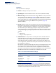
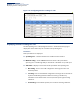
Table Of Contents
- How to Use This Guide
- Contents
- Figures
- Tables
- Getting Started
- Web Configuration
- Using the Web Interface
- Basic Management Tasks
- Displaying System Information
- Displaying Hardware/Software Versions
- Configuring Support for Jumbo Frames
- Displaying Bridge Extension Capabilities
- Managing System Files
- Setting the System Clock
- Configuring the Console Port
- Configuring Telnet Settings
- Displaying CPU Utilization
- Displaying Memory Utilization
- Stacking
- Resetting the System
- Interface Configuration
- VLAN Configuration
- Address Table Settings
- Spanning Tree Algorithm
- Congestion Control
- Class of Service
- Quality of Service
- VoIP Traffic Configuration
- Security Measures
- AAA (Authentication, Authorization and Accounting)
- Configuring User Accounts
- Web Authentication
- Network Access (MAC Address Authentication)
- Configuring HTTPS
- Configuring the Secure Shell
- Access Control Lists
- Setting a Time Range
- Showing TCAM Utilization
- Setting the ACL Name and Type
- Configuring a Standard IPv4 ACL
- Configuring an Extended IPv4 ACL
- Configuring a Standard IPv6 ACL
- Configuring an Extended IPv6 ACL
- Configuring a MAC ACL
- Configuring an ARP ACL
- Binding a Port to an Access Control List
- Configuring ACL Mirroring
- Showing ACL Hardware Counters
- ARP Inspection
- Filtering IP Addresses for Management Access
- Configuring Port Security
- Configuring 802.1X Port Authentication
- DoS Protection
- IPv4 Source Guard
- IPv6 Source Guard
- DHCP Snooping
- Basic Administration Protocols
- Configuring Event Logging
- Link Layer Discovery Protocol
- Power over Ethernet
- Simple Network Management Protocol
- Configuring Global Settings for SNMP
- Setting the Local Engine ID
- Specifying a Remote Engine ID
- Setting SNMPv3 Views
- Configuring SNMPv3 Groups
- Setting Community Access Strings
- Configuring Local SNMPv3 Users
- Configuring Remote SNMPv3 Users
- Specifying Trap Managers
- Creating SNMP Notification Logs
- Showing SNMP Statistics
- Remote Monitoring
- Switch Clustering
- Ethernet Ring Protection Switching
- Connectivity Fault Management
- Configuring Global Settings for CFM
- Configuring Interfaces for CFM
- Configuring CFM Maintenance Domains
- Configuring CFM Maintenance Associations
- Configuring Maintenance End Points
- Configuring Remote Maintenance End Points
- Transmitting Link Trace Messages
- Transmitting Loop Back Messages
- Transmitting Delay-Measure Requests
- Displaying Local MEPs
- Displaying Details for Local MEPs
- Displaying Local MIPs
- Displaying Remote MEPs
- Displaying Details for Remote MEPs
- Displaying the Link Trace Cache
- Displaying Fault Notification Settings
- Displaying Continuity Check Errors
- OAM Configuration
- UDLD Configuration
- Multicast Filtering
- Overview
- Layer 2 IGMP (Snooping and Query for IPv4)
- Configuring IGMP Snooping and Query Parameters
- Specifying Static Interfaces for a Multicast Router
- Assigning Interfaces to Multicast Services
- Setting IGMP Snooping Status per Interface
- Filtering IGMP Query Packets and Multicast Data
- Displaying Multicast Groups Discovered by IGMP Snooping
- Displaying IGMP Snooping Statistics
- Filtering and Throttling IGMP Groups
- MLD Snooping (Snooping and Query for IPv6)
- Layer 3 IGMP (Query used with Multicast Routing)
- Multicast VLAN Registration for IPv4
- Multicast VLAN Registration for IPv6
- IP Configuration
- IP Services
- General IP Routing
- Configuring Router Redundancy
- Unicast Routing
- Overview
- Configuring the Routing Information Protocol
- Configuring General Protocol Settings
- Clearing Entries from the Routing Table
- Specifying Network Interfaces
- Specifying Passive Interfaces
- Specifying Static Neighbors
- Configuring Route Redistribution
- Specifying an Administrative Distance
- Configuring Network Interfaces for RIP
- Displaying RIP Interface Settings
- Displaying Peer Router Information
- Resetting RIP Statistics
- Configuring the Open Shortest Path First Protocol (Version 2)
- Defining Network Areas Based on Addresses
- Configuring General Protocol Settings
- Displaying Administrative Settings and Statistics
- Adding an NSSA or Stub
- Configuring NSSA Settings
- Configuring Stub Settings
- Displaying Information on NSSA and Stub Areas
- Configuring Area Ranges (Route Summarization for ABRs)
- Redistributing External Routes
- Configuring Summary Addresses (for External AS Routes)
- Configuring OSPF Interfaces
- Configuring Virtual Links
- Displaying Link State Database Information
- Displaying Information on Neighboring Routers
- Multicast Routing
- Appendices
- Glossary
- Index

Chapter 7
| Spanning Tree Algorithm
Configuring Interface Settings for STA
– 224 –
Parameters
These parameters are displayed:
◆ Interface – Displays a list of ports or trunks.
◆ Spanning Tree – Enables/disables STA on this interface. (Default: Enabled)
◆ BPDU Flooding - Enables/disables the flooding of BPDUs to other ports when
global spanning tree is disabled (page 217) or when spanning tree is disabled
on a specific port. When flooding is enabled, BPDUs are flooded to all other
ports on the switch or to all other ports within the receiving port’s native VLAN
as specified by the Spanning Tree BPDU Flooding attribute (page 217).
(Default: Enabled)
◆ Priority – Defines the priority used for this port in the Spanning Tree Protocol.
If the path cost for all ports on a switch are the same, the port with the highest
priority (i.e., lowest value) will be configured as an active link in the Spanning
Tree. This makes a port with higher priority less likely to be blocked if the
Spanning Tree Protocol is detecting network loops. Where more than one port
is assigned the highest priority, the port with lowest numeric identifier will be
enabled.
■
Default: 128
■
Range: 0-240, in steps of 16
◆ Admin Path Cost – This parameter is used by the STA to determine the best
path between devices. Therefore, lower values should be assigned to ports
attached to faster media, and higher values assigned to ports with slower
media. Note that path cost takes precedence over port priority. (Range: 0 for
auto-configuration, 1-65535 for the short path cost method
7
, 1-200,000,000 for
the long path cost method)
By default, the system automatically detects the speed and duplex mode used
on each port, and configures the path cost according to the values shown
below. Path cost “0” is used to indicate auto-configuration mode. When the
short path cost method is selected and the default path cost recommended by
the IEEE 8021w standard exceeds 65,535, the default is set to 65,535.
7. Refer to “Configuring Global Settings for STA” on page 217 for information on setting the
path cost method.The range displayed on the STA interface configuration page shows the
maximum value for path cost. However, note that the switch still enforces the rules for path
cost based on the specified path cost method (long or short).
Table 11: Recommended STA Path Cost Range
Port Type IEEE 802.1D-1998 IEEE 802.1w-2001
Ethernet 50-600 200,000-20,000,000
Fast Ethernet 10-60 20,000-2,000,000
Gigabit Ethernet 3-10 2,000-200,000
10G Ethernet 1-5 200-20,000