
Web Management Guide-R06
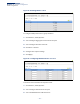
Table Of Contents
- How to Use This Guide
- Contents
- Figures
- Tables
- Getting Started
- Web Configuration
- Using the Web Interface
- Basic Management Tasks
- Displaying System Information
- Displaying Hardware/Software Versions
- Configuring Support for Jumbo Frames
- Displaying Bridge Extension Capabilities
- Managing System Files
- Setting the System Clock
- Configuring the Console Port
- Configuring Telnet Settings
- Displaying CPU Utilization
- Displaying Memory Utilization
- Stacking
- Resetting the System
- Interface Configuration
- VLAN Configuration
- Address Table Settings
- Spanning Tree Algorithm
- Congestion Control
- Class of Service
- Quality of Service
- VoIP Traffic Configuration
- Security Measures
- AAA (Authentication, Authorization and Accounting)
- Configuring User Accounts
- Web Authentication
- Network Access (MAC Address Authentication)
- Configuring HTTPS
- Configuring the Secure Shell
- Access Control Lists
- Setting a Time Range
- Showing TCAM Utilization
- Setting the ACL Name and Type
- Configuring a Standard IPv4 ACL
- Configuring an Extended IPv4 ACL
- Configuring a Standard IPv6 ACL
- Configuring an Extended IPv6 ACL
- Configuring a MAC ACL
- Configuring an ARP ACL
- Binding a Port to an Access Control List
- Configuring ACL Mirroring
- Showing ACL Hardware Counters
- ARP Inspection
- Filtering IP Addresses for Management Access
- Configuring Port Security
- Configuring 802.1X Port Authentication
- DoS Protection
- IPv4 Source Guard
- IPv6 Source Guard
- DHCP Snooping
- Basic Administration Protocols
- Configuring Event Logging
- Link Layer Discovery Protocol
- Power over Ethernet
- Simple Network Management Protocol
- Configuring Global Settings for SNMP
- Setting the Local Engine ID
- Specifying a Remote Engine ID
- Setting SNMPv3 Views
- Configuring SNMPv3 Groups
- Setting Community Access Strings
- Configuring Local SNMPv3 Users
- Configuring Remote SNMPv3 Users
- Specifying Trap Managers
- Creating SNMP Notification Logs
- Showing SNMP Statistics
- Remote Monitoring
- Switch Clustering
- Ethernet Ring Protection Switching
- Connectivity Fault Management
- Configuring Global Settings for CFM
- Configuring Interfaces for CFM
- Configuring CFM Maintenance Domains
- Configuring CFM Maintenance Associations
- Configuring Maintenance End Points
- Configuring Remote Maintenance End Points
- Transmitting Link Trace Messages
- Transmitting Loop Back Messages
- Transmitting Delay-Measure Requests
- Displaying Local MEPs
- Displaying Details for Local MEPs
- Displaying Local MIPs
- Displaying Remote MEPs
- Displaying Details for Remote MEPs
- Displaying the Link Trace Cache
- Displaying Fault Notification Settings
- Displaying Continuity Check Errors
- OAM Configuration
- UDLD Configuration
- Multicast Filtering
- Overview
- Layer 2 IGMP (Snooping and Query for IPv4)
- Configuring IGMP Snooping and Query Parameters
- Specifying Static Interfaces for a Multicast Router
- Assigning Interfaces to Multicast Services
- Setting IGMP Snooping Status per Interface
- Filtering IGMP Query Packets and Multicast Data
- Displaying Multicast Groups Discovered by IGMP Snooping
- Displaying IGMP Snooping Statistics
- Filtering and Throttling IGMP Groups
- MLD Snooping (Snooping and Query for IPv6)
- Layer 3 IGMP (Query used with Multicast Routing)
- Multicast VLAN Registration for IPv4
- Multicast VLAN Registration for IPv6
- IP Configuration
- IP Services
- General IP Routing
- Configuring Router Redundancy
- Unicast Routing
- Overview
- Configuring the Routing Information Protocol
- Configuring General Protocol Settings
- Clearing Entries from the Routing Table
- Specifying Network Interfaces
- Specifying Passive Interfaces
- Specifying Static Neighbors
- Configuring Route Redistribution
- Specifying an Administrative Distance
- Configuring Network Interfaces for RIP
- Displaying RIP Interface Settings
- Displaying Peer Router Information
- Resetting RIP Statistics
- Configuring the Open Shortest Path First Protocol (Version 2)
- Defining Network Areas Based on Addresses
- Configuring General Protocol Settings
- Displaying Administrative Settings and Statistics
- Adding an NSSA or Stub
- Configuring NSSA Settings
- Configuring Stub Settings
- Displaying Information on NSSA and Stub Areas
- Configuring Area Ranges (Route Summarization for ABRs)
- Redistributing External Routes
- Configuring Summary Addresses (for External AS Routes)
- Configuring OSPF Interfaces
- Configuring Virtual Links
- Displaying Link State Database Information
- Displaying Information on Neighboring Routers
- Multicast Routing
- Appendices
- Glossary
- Index

Chapter 4
| Interface Configuration
Port Configuration
– 141 –
Command Usage
◆ Cable diagnostics are performed using Digital Signal Processing (DSP) test
methods. DSP analyses the cable by sending a pulsed signal into the cable, and
then examining the reflection of that pulse.
◆ Cable diagnostics can only be performed on twisted-pair media.
◆ This cable test is only accurate for cables 7 - 100 meters long.
◆ The test takes approximately 5 seconds. The switch displays the results of the
test immediately upon completion, including common cable failures, as well as
the status and approximate length to a fault.
◆ Potential conditions which may be listed by the diagnostics include:
■
OK: Correctly terminated pair
■
Open: Open pair, no link partner
■
Short: Shorted pair
■
Not Supported: This message is displayed for any Gigabit Ethernet ports
linked up at a speed lower than 1000 Mbps, or for any 10G Ethernet ports.
■
Impedance mismatch: Terminating impedance is not in the reference
range.
◆ Ports are linked down while running cable diagnostics.
Parameters
These parameters are displayed:
◆ Port – Switch port identifier.
◆ Type – Displays media type. (GE – Gigabit Ethernet, Other – SFP
3
/SFP+)
◆ Link Status – Shows if the port link is up or down.
◆ Test Result – The results include common cable failures, as well as the status
and approximate distance to a fault, or the approximate cable length if no fault
is found.
To ensure more accurate measurement of the length to a fault, first disable
power-saving mode on the link partner before running cable diagnostics.
For link-down ports, the reported distance to a fault is accurate to within +/- 2
meters. For link-up ports, the accuracy is +/- 10 meters.
◆ Last Updated – Shows the last time this port was tested.
◆ Test – Initiates cable test.
3. ECS4620-28F and ECS4620-28F-DC/28F-2AC